Render Setup Editor
Table of Contents
- Render Setup Editor
- Warping and Soft-Edging
Following recent Microsoft Windows Updates to Full Screen Optimization, synchronization between frames across multiple GPU outputs may not be as predictable as before.
Enabling Mosaic Mode can solve this issue. In most cases, the timing discrepancies are minimal and unlikely to be noticeable to users. However, in scenarios where multiple displays are arranged with adjacent pixels, such as two touching LED walls using two outputs, such discrepancies may become more apparent. To ensure optimal synchronization in these situations, we recommend enabling Mosaic Mode. This only occurs when using multiple outputs on one GPU. If only one output is being used, this issue does not occur even if using multiple GPUs in one machine.
Introduction
The Render Setup Editor is part of the Ventuz Configuration and is used to create a configuration for complex display walls.
Render Setup configurations are now stored with the Project inside the Render Setup folder as a .vren! And are not inside the Configuration folder inside the puplic documents anymore.
The content and Previsualization Scenes for such displays may come from a single or multiple Ventuz machines. Generally speaking, the Render Setup Editor is used to solve following problem: Display Ventuz content correctly on an arbitrarily complex display wall built up of N displays connected to M machines.
To learn more about using multiple machines and clustering take a look here.
In other words, the Render Setup is the link between the design canvas and the actual physical output of the graphics card(s). Be it a simple bezel compensation, a projection blend, a 4 x 1 stripe of LED panels that is fed from one output, to complex setups with rotated displays.
User Interface
The editor consists of two main modes the Layout Mode and Mapping mode. Inside the Layout Mode, Compositions and Screens are configured; while in the Mapping Mode screens are assigned to physical outputs.
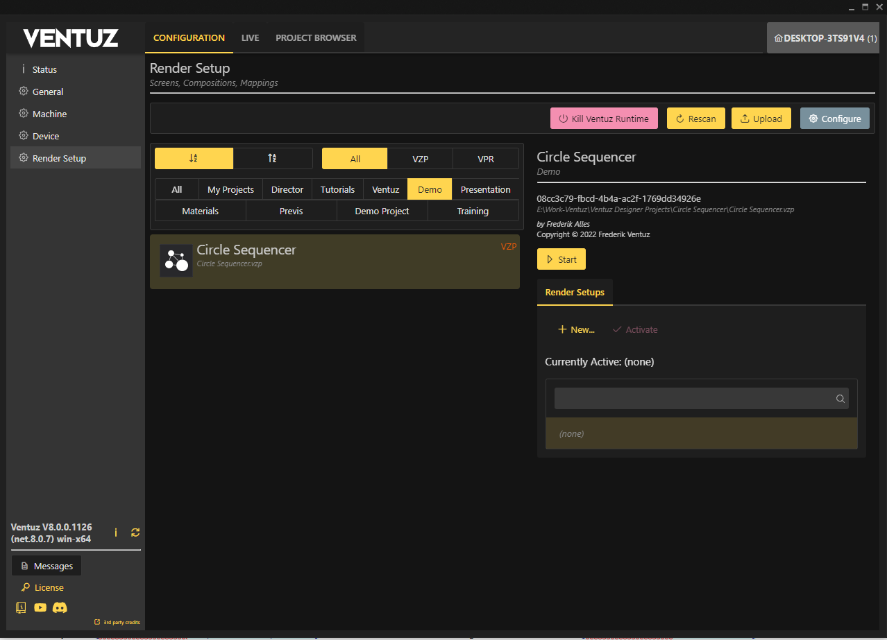
To open the Render Setup editor, open the Configuration Editor and open the Configuration tab, on the left side you will find a entry called Render Setups. Now select the Project this setup should be for. Create a new Render Setup by clicking the button on the right side of the window.
Import and Export Render Setup
It is possible to Import and Export existing Render Setups to and from Projects and to import from previous versions of Ventuz when using the Migration assist tool.
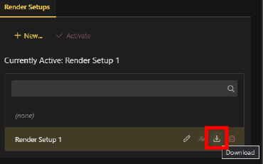
Export
To export a Render Setup, hover over the "Download" button and click. Save the file in a desired folder on your hard drive.
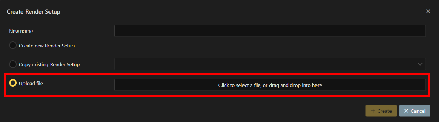
Import
To Import an existing Render Setup file, Click on "New...", in the pop-up select "Import Render Setup" and navigate to the location the desired Render Setup file is stored.
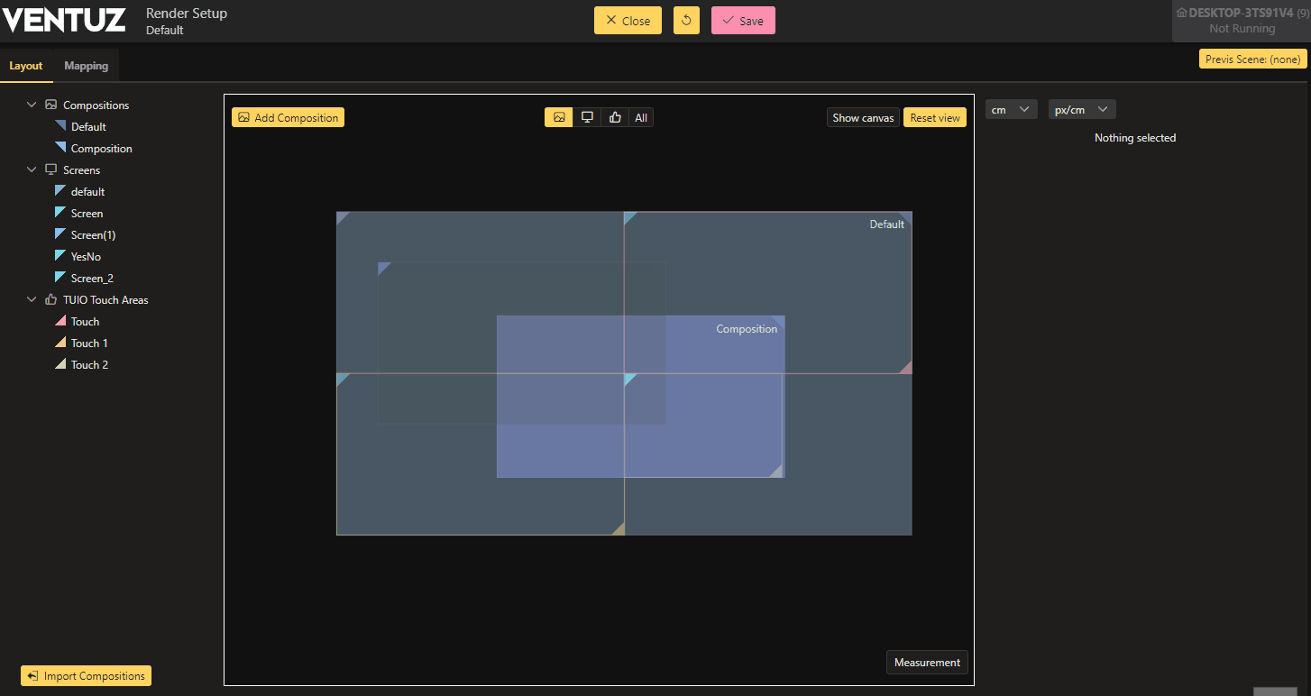
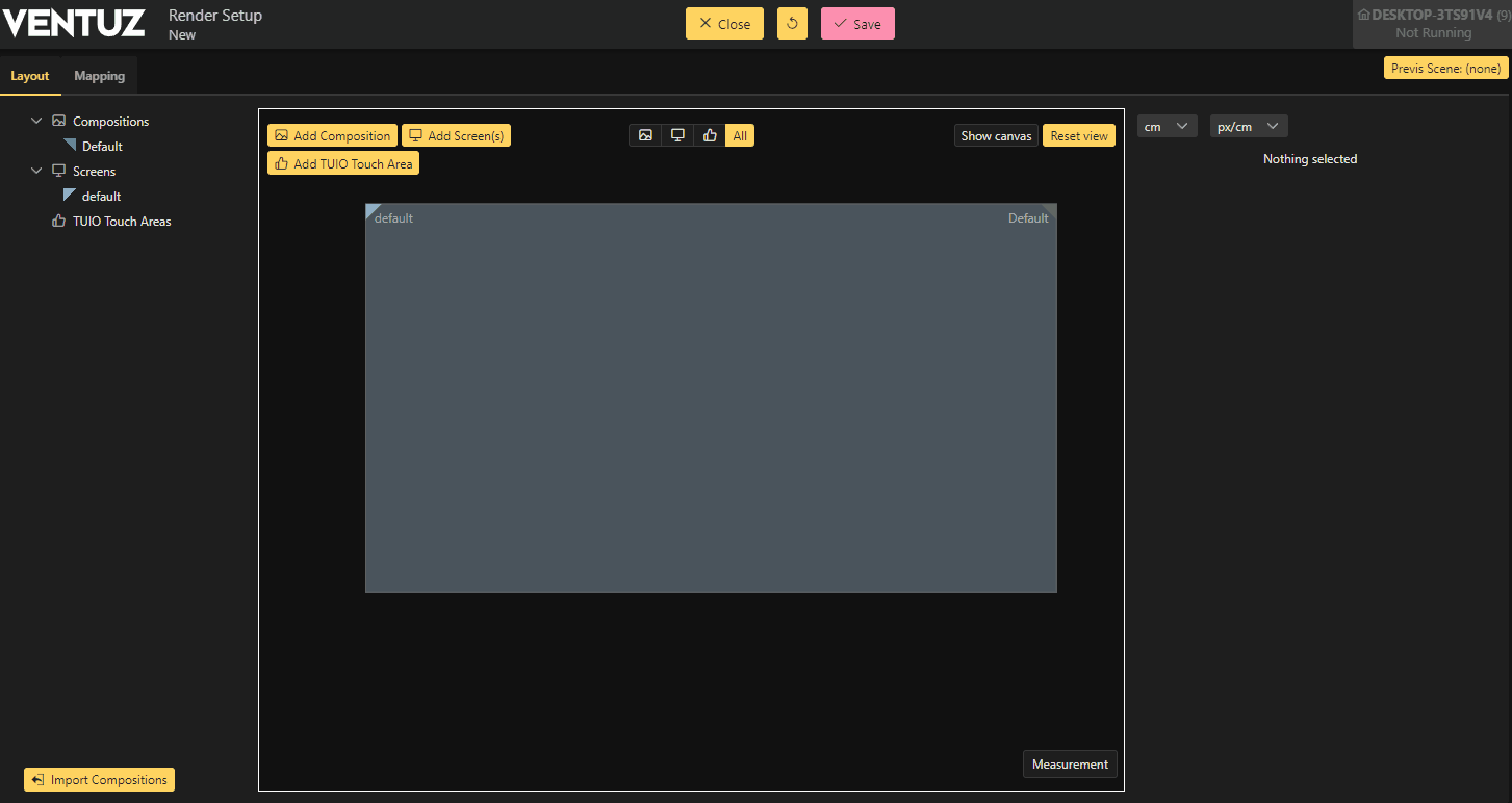
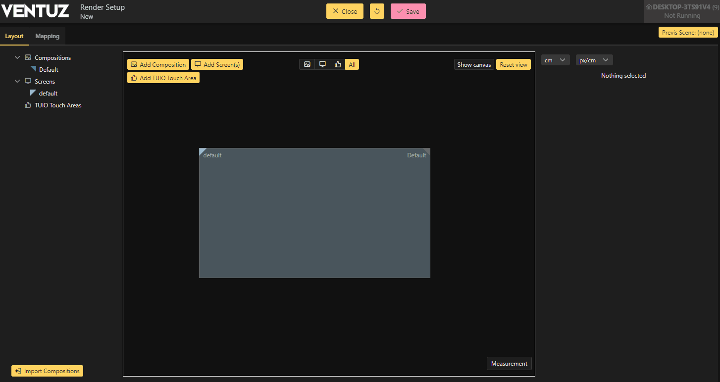
Layout Mode
Once the new Render Setup is created, the Render Setup window will automatically open in the Layout Mode.
To edit an existing Render Setup click on the Pencil Icon inside of the existing Render Setup.
Generally speaking this is the mode where you set the stage for you presentation, add screens and use compositions to set the frame for your rendering. To learn more about the handling of our new output system read this page.
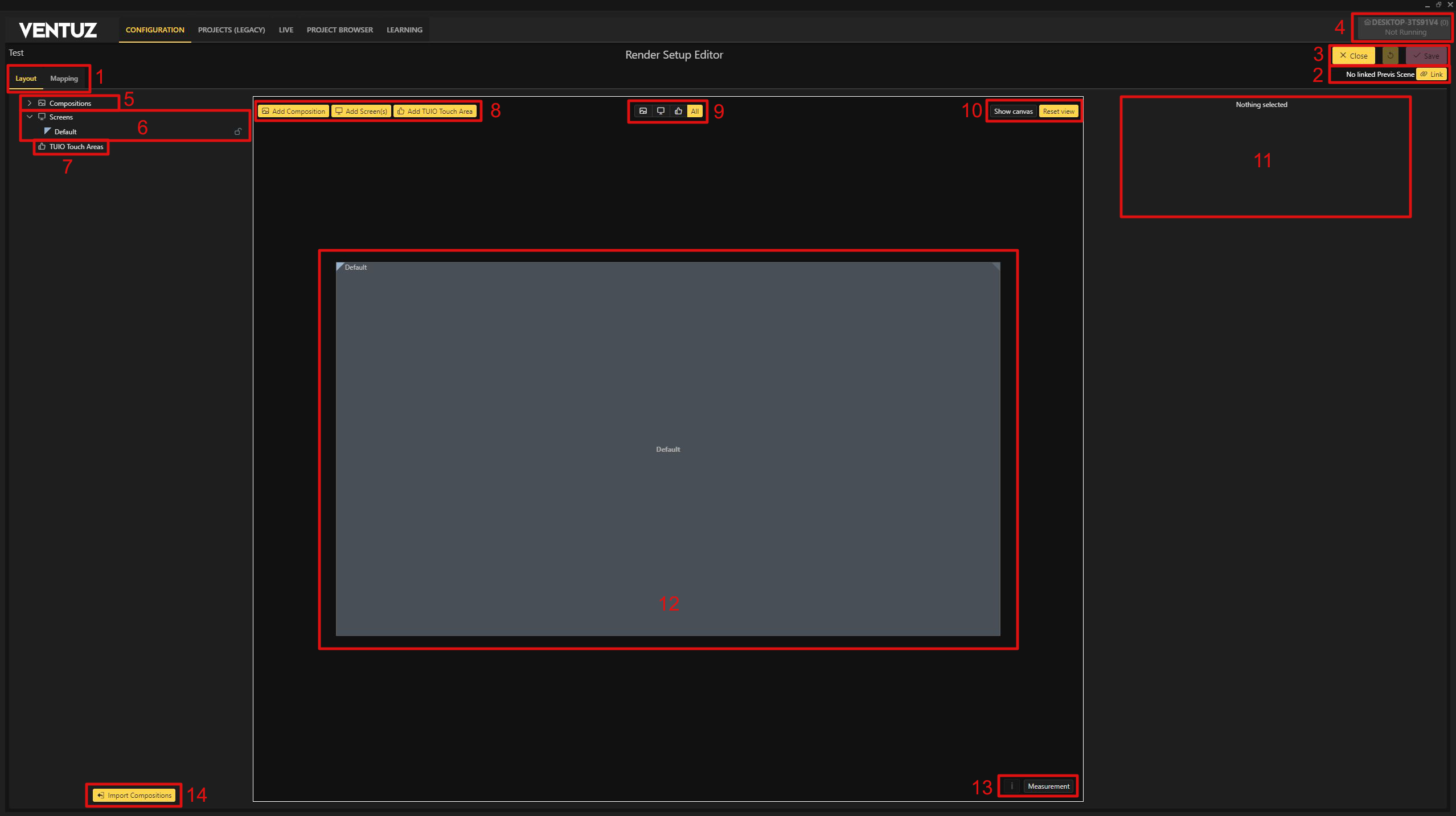
1. Mode Change:
- Change between the Layout and Mapping mode
2. Previs:
- Select Previsualization Scenes currently available inside your .vzp Ventuz Project via the Pencil icon and import them, make sure you saved them recently after a upgrade to a higher version or you wont be able to see your scenes.
Previsualization scenes wont have a layout mode since these screens are placed in a 3D world and these positions can't be converted to function in the Layout mode. Instead it uses the Mapping mode only to assign these screens to Outputs
3. Close and Save:
- Close: Closes the Render Setup Editor
- Save: Saves the recent changes and applies them. This will also apply it to a running runtime which can interrupt the rendering!
- Undo: Undo your changes, CTRL+Z also works.
- Live: Click this Checkbox to see your changes in real time when the associated project is running in Ventuz Runtime.
Using the Live mode will interrupt the rendering on every change!
4. Machine Selection:
- Currently selected machine. Select the appropriate machine before going into the Editor.
5. Compositions:
- Select and add Compositions inside the Tree View. Via its possible to add either Instances or new Compositions. A Double click lets you change the name, this is also possible inside the Properties Window (11) The Default Composition name cannot be changed. Deleting is done by and using the drop down menu. Here you can also change the Rendering Order of the compositions. If multiple Compositions are placed on the same output the render order may need to be changed to achieve your desired results. To accomplish this, simply drag+drop to change it.
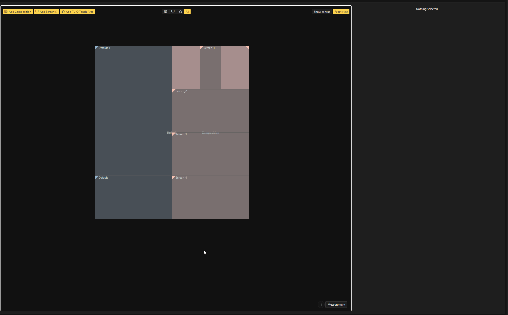
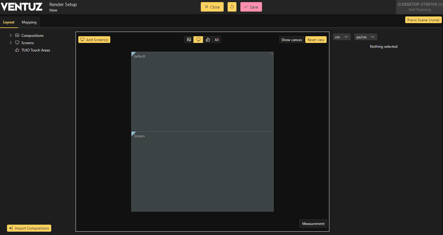
6. Screens: Select via and add Screens with the . Adding Screens and Compositions is also possible by right clicking inside the view window depending on the mode you are in. 7. TUIO Touch areas:
- Add or delete TUIO Touch areas to define which parts of your setup should be interactive. Windows touch is not assignable through this area. Use the Multi capabilities and touch groups for Windows Touch that can be found inside of the Machine Configuration Window.
8. Contextual Controls:
- Depending on the mode you are in these buttons offers the functions to add objects. Like you can by using the tree view or inside the view window.
9. Mode Selection:
- The Render setup editor has different "editing" modes. To only edit Compositions use the button on the left. Right beside that is the Screens edit button and besides that you can find the Touch area edit mode. Or use the ALL button to be able to select everything either in a multi selection or one by one.
10. View Options:
- Reset View
- Reset the workspace view to 0.0.
- Show Canvas
- Shows the Canvas(es)
11. Property Editor:
- Holds the properties of selected elements. Measurements can be in metric or imperial units.
12. Workspace:
Displays the created elements and allows editing of these elements. See Shortcuts for full list of hotkeys.
- Use Drag to move elements around
- Hold down the middle mouse button to pan the view
- to open the context menu
- Using the scroll wheel will zoom the view in and out
- multiple times on the same spot will click through items so selecting the ones beneath is easier
13. Measurement Tool:
- Enables the Measurement Tool, use this to measure distances between elements. Displayed in centimeters. on a edge or corner of a element and drag it over to a second point.
14. Import Compositions:
- Import Composition layer from a scene. This way you dont have to replicate what you already did inside the Designer.
Render Setup Elements
Compositions
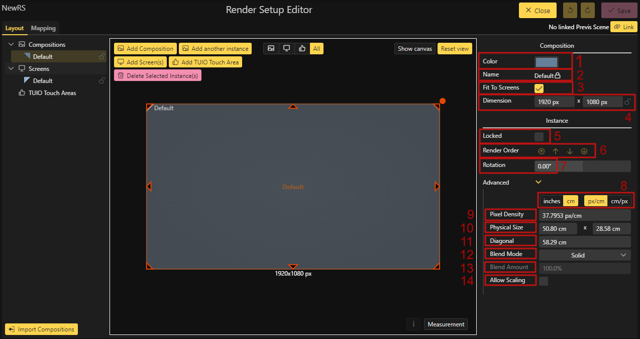
1. Color
- Changes the color of the Composition
2. Name
- Changes the Name of the Composition. This is locked for Default Compositions
3.Fit to Screen
- This is a unique feature for the Default Composition, when turned off the composition wont scale with screens moved inside it anymore
4. Dimension
- Sets the Virtual Dimension for the Composition
5. Lock
- Locks the selected composition or screen in position and size.
6. Render Order
- Changes the Rendering Order
7. Rotation
- Displays the current rotation value of the selected element. This can be changed by dragging the property, directly typing in it or by using the dot in the upper right corner of the view port
8. Units of measurement
- Choose the unit of measurement from centimeter to inches. And change between pixel per centimeter or centimeter per pixel.
9. Pixel Density
- Sets the Pixel Density per cm/inch for the Composition
10. Physical Size
- Sets the Physical size of the Composition
11. Diagonal
- The Diagonal width of the Composition
12. Blend Mode
- Sets the Blending mode for the Compositions. This only applies for stacked compositions
13. Blend Amount
- The Amount of blending, lower values means less blending of the elements
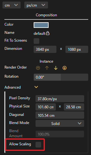
14. Allow Scaling
- Enables the Scaling function, only usable for instanced content
Screens
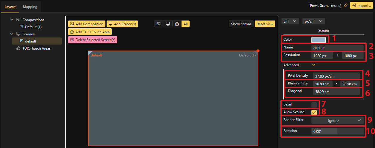
1. Color
- Changes the color of the Screen
2. Name
- Changes the Name of the Screen.
3. Resolution
- Sets the Virtual Resolution of the Screen
4. Pixel Density
- Sets the Pixel Density per cm/inch for the Screen
5. Physical Size
- Sets the Physical size of the Screen
6. Diagonal
- The Diagonal width of the Screen
7. Bezel
- Activates the Bezel function for the selected screen/s
8. Allow Scaling
- Enables the Scaling function, only usable for instanced content
9. Render Filter
- Use this to filter out specific content by choosing different Render Filter groups, only functioning in conjunction with the Render Filter node
10. Rotation
- Displays the current rotation value of the selected element. This can be changed by dragging the property, directly typing in it or by using the dot in the upper right corner of the view port
TUIO Touch Areas
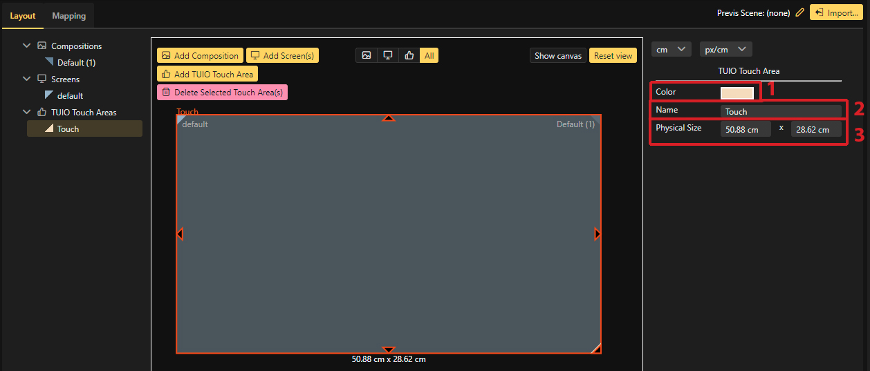
1. Color
- Changes the color of the Touch Area
2. Name
- Changes the Name of the Touch Area
5. Physical Size
- Sets the Physical size of the Touch Area
Measurement Tool
By using the measurement button in the lower right corner the user is able to measure distances between different elements in centimeters or inches. Clicking on the measurement button will toggle all measurements on and off.
Set a measurement:
on an edge or corner of an element and drag it over to a second point to create a measurement.
To adjust existing points, hold CTRL and click&drag on a point to adjust.
Holding SHIFT while dragging a point, they will snap lines at 45° increments while drawing them.
All of the markers are sticky; they will stay attached to the same point on an object if you change the size, rotation or pixel density.
Deleting Measurements:
By on a existing measurement and hitting DEL will delete the measurement line. Alternatively you can also hold CTRL and drag a point into empty space to delete it.
Measurement Info Box
With the measurement info box it is possible to measure different objects with different DPI or Px/cm and the different pixel distances.
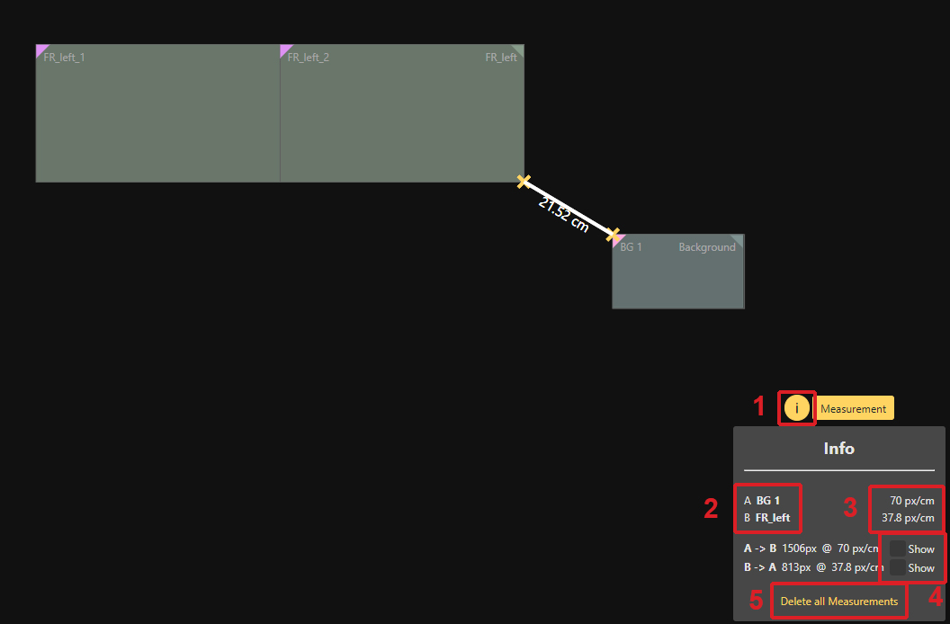
1: Info Box Button
- Enables or disables the Info Box
2: Names
- Names of the two objects connected by the selected measurement
3: Current Dots per inch / pixel per cm
- Shows the pixel per centimeter of the corresponding object
4: Show button
- Activate the show button and changes the label on the currently selected measurement.
5: Delete all measurements
- Button to delete all measurements
Changing the Render Order
When stacking Compositions on to each other it may be necessary to change their render order. To do that, simply drag and drop the Composition to the desired place in the Tree view. As always in Ventuz, the Render order starts from the top down.
Blending
Blending can be adjusted for stacked compositions by using the properties for each Composition.
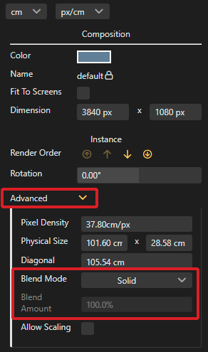
Solid: No blending is used
Alpha: Enables Alpha Blending
Add: Additive RGB blending
Multiplicative: Multiplies the RGB blending
Smooth Additive: Smoother additive blending
Keep in mind stacked screens inside the output do not blend!
Composition Instancing
Instancing Compositions can be used to show the same content multiple times, in different positions or different resolutions. When "Allow Scaling" is enabled, Ventuz will render the scene elements one time and scale them to fit the corresponding Compositions. Scaling saves system resources. Ensure the aspect ratio is correct for these instanced Compositions; otherwise, your content might end up stretched or squished.
Default Composition
The Default Composition inside the Render Setup Editor behaves differently than other ones.
This Composition will automatically scale with screens that are inside this Composition. The Name of the Default Composition can't be changed.
In order to free screens of the automatic scaling inside the Default Composition uncheck the "Fit to Screen" property on the Default Composition or use the scaling handles of the composition and remove the Screen from it. Deleting the Default Composition inside the Render Setup Editor will not break anything inside the Designer. Still the Default Composition Layer will be present when another Composition layer is inserted but can be safely ignored.
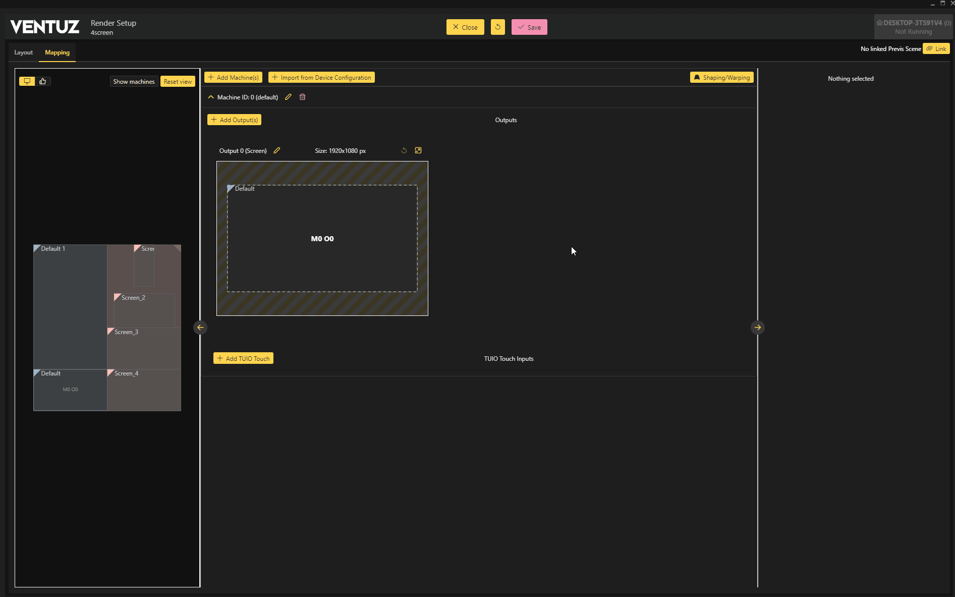
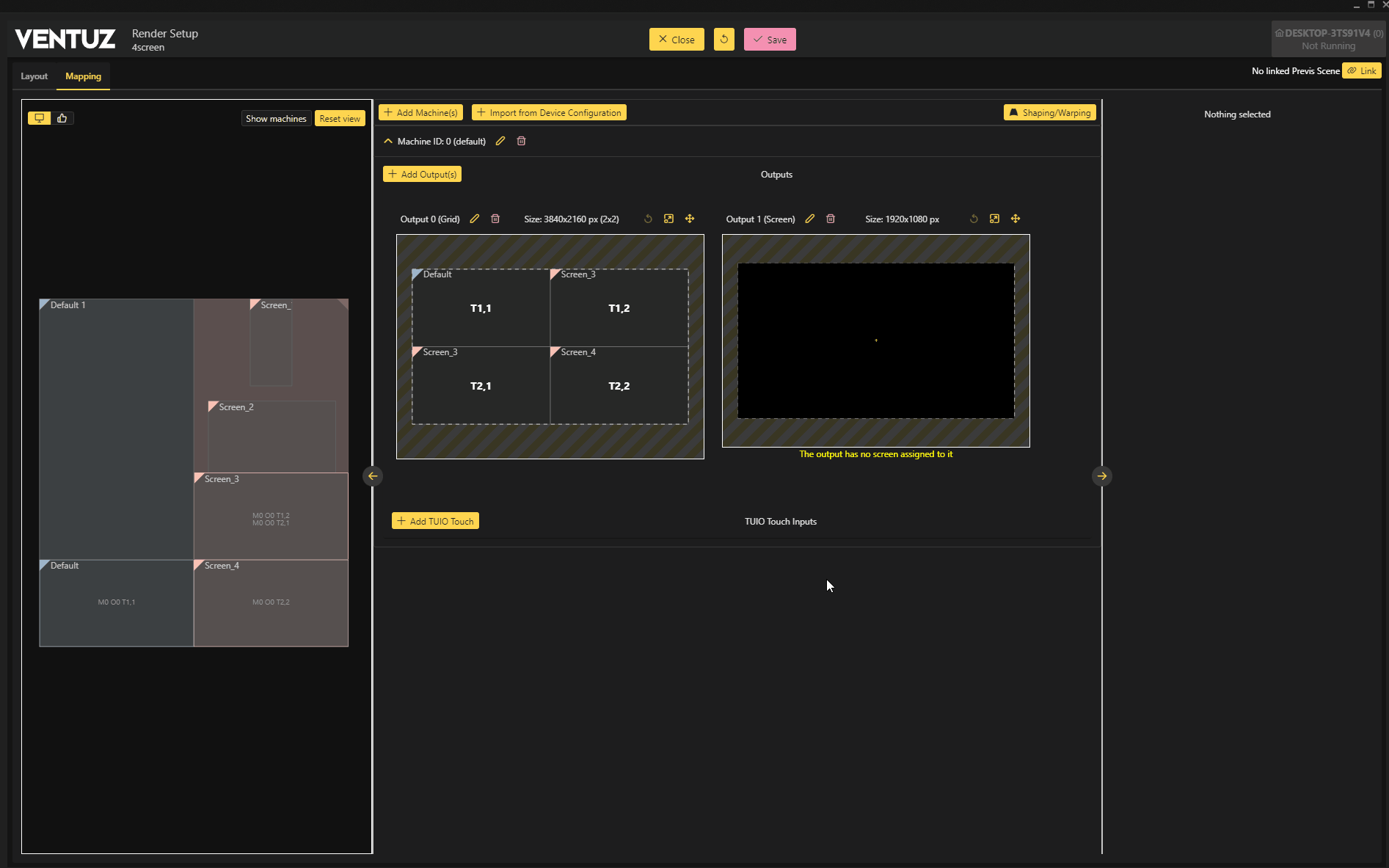
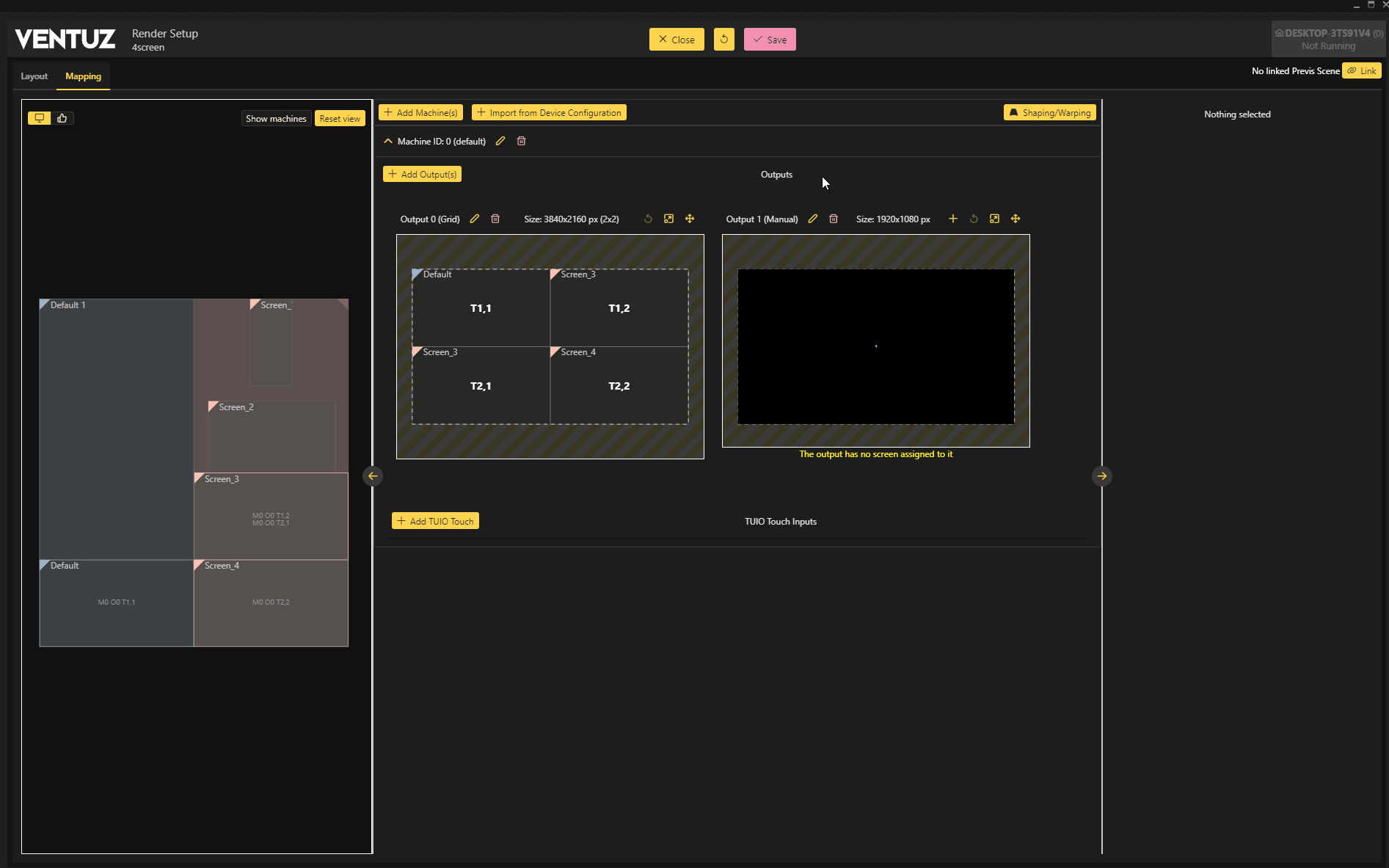
Mapping Mode
With the Mapping mode it is possible to assign Screens to Outputs, add new machines, or shape and warp Outputs.
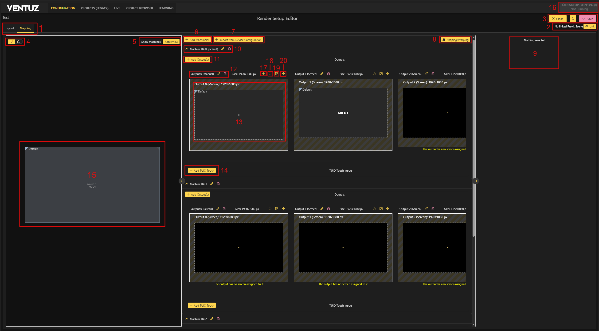
1. Mode Change:
- Change between the Layout and Mapping Mode.
2. Previs:
- Select Previsualization Scenes currently available inside your .vzp Ventuz Project and import them into the Render Setup.
3. Close and Save:
- Close: Closes the Render Setup Editor
- Save: Saves the recent changes and applies them.
- If the Render Setup that you're editing is active, clicking Save will apply it to a running Runtime. This can interrupt the rendering of each Runtime!
- Undo: Undo your changes, CTRL+Z also works.
4. Mode Selection:
- The Mapping mode has two different modes to show; All screens, or All Touch areas separately.
5. View Options:
- Show Machines: Will highlight machine borders with a white dotted line.
- Reset View: Resets the workspace view to 0.0
6. Add machines:
- Adds another machine to the Output list. Here you can also setup things like the Machine ID how many outputs that machine has and so on.
7. Import Device Configuration:
- This lets you import complete Device configurations currently available on the selected machine. Take a look into the Import Device Configuration section to learn more.
8. Shaping & Warping:
- Select a screen to Warp and use this button to get into the Shaping&Warping editor.
9. Property Editor:
- Holds the properties of selected elements. Measurements can be in Metric or Imperial.
10. Machine Options:
- Use the Pencil to edit the currently used MachineID. Or use the bucket to delete the machine with its outputs. This will also use your current machine ID when creating the Render Setup.
11. Add Outputs:
- Add outputs to the machine.
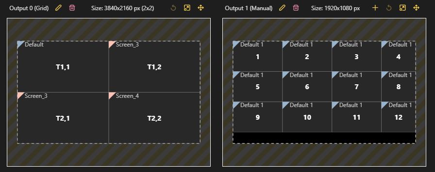
12. Output Options: There are three output types available:
- Single Screen: the output will only use one screen.
- Grid: Allows to assign multiple screens to one output.
- Manual: Adjust the output resolution and screen sizes manually.
- Name: Here you can change the name of the current output. When imported from a device configuration this will have the name according to that configuration.
13. Output Workspace:
- Shows the output in its chosen configuration. Selectable with the . Pan the view with the middle mouse button. And use the scroll wheel to zoom in and out. When set to manual and dropping a screen onto it you can hold SHIFT to tile the screen directly.
14. TUIO Touch inputs:
- Add TUIO touch inputs to the output. It is possible to either use the Touch areas in the Layout mode or directly assign complete screens to a TUIO touch input.
15. Workspace:
- Workspace shows the machine boarder as well as all configured Screens and Touch areas. These can be dragged and dropped on to outputs to configure them. Multi select is also possible.
16. Selected Machine/Group:
- Shows the machine or cluster group that is currently selected.
17. Adding cuts:
- When the output is put to Manual mode you can use this button to add cuts.
18. Reset of the view:
- Resets the view to the center.
19. Maximize output:
- Use this to maximizie one output to a bigger size, which makes working with a lot of smaller cuts alot easier. You can also double click the output to open and close it. Also navigating through the outputs is possible with the arrow buttons on the top when maximized.
 20. Moving of outputs:
- With this button you can move outputs to a different slot, but keep in mind that these outputs represent your physical GPU outputs! First output will also always be the top one in your Device configuration. And if these not match correctly the outputs will render incorrectly. We advice using the configuration import to minimize the risk of such issues.
Import Device Configuration
After clicking on the Device Configuration Import button you will be greeted with this small helper pop up.
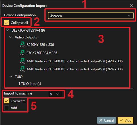
1: Device Configuration:
- Choose a Configuration from the drop down menu. This will show all available Device Configurations.
2: Collapse all:
- Collapse the whole tree,
3: Configuration Overview:
- This shows an overview of the content inside the selected Device Configuration. The names of the outputs will be added to the outputs in the Mapping Mode.
4: Choosing a machine to import to:
- Here you choose to which machine the outputs should be added. IDs are taken from the currently configured IDs inside the Machine Configuration.
5: Choose to overwrite or add:
- Choose if you want to overwrite the current mapping or add (append) it to the existing ones.
For a Cluster Configuration Imports, only the currently active configurations from the machines inside that group can be used. Also note that you have to choose the correct group before opening a new Render Setup for that cluster!
Coordinate Space
The Screens and Compositions in the Render Setup Editor lie in a real world sized coordinate space. The origin of this coordinate space is the middle starting with (0.0.).
Logical vs. Visual Resolution
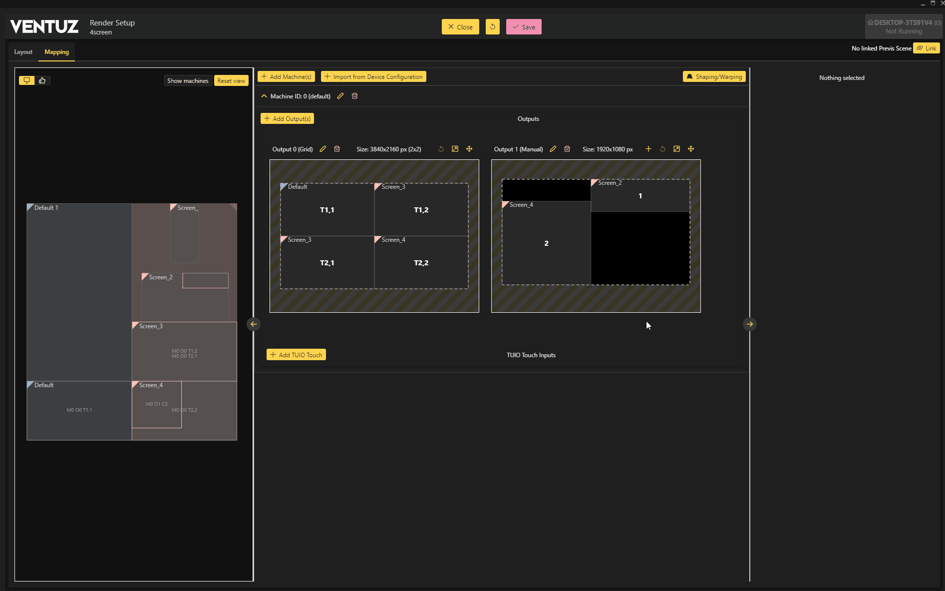
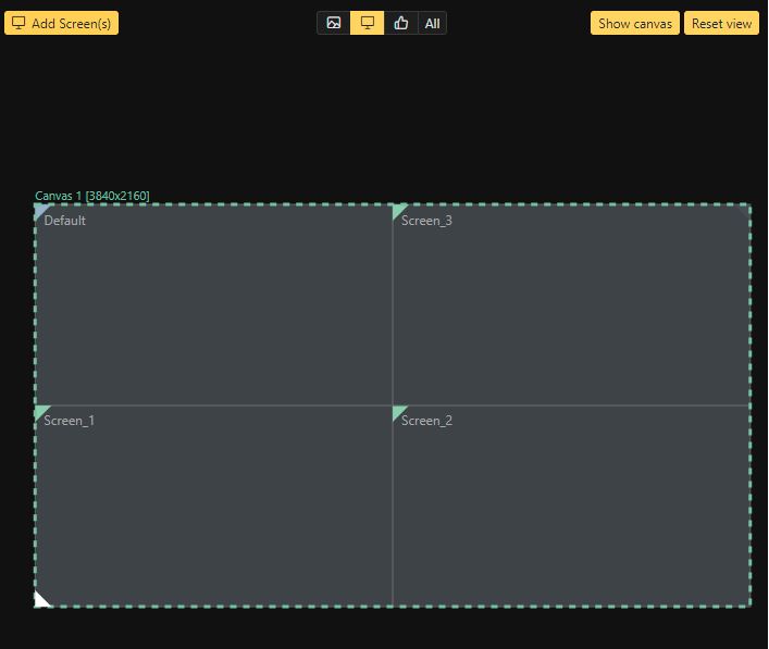
In the context of the Render Setup configuration we talk about Logical and Visual Resolutions. These terms will be explained here. The logical resolution of a machine can be defined by the Mosaic or Eyefinity configuration of the graphics board. A 2x2 display setup with a resolution of 1920 x 1080 px per display has a logical resolution of 3840 x 2160 pixels.
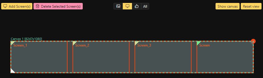
The visual resolution however is defined by final position of the displays in the Render Setup configuration. In the example below the displays are arranged horizontally and have bezel between each other. This leads to the visual resolution of 8247 x 1080 pixel.
The maximum visual resolution for a GPU currently is 16384 x 16384 pixels!
Manipulating a Render Setup
Selecting and Moving Elements
Elements can be selected by simply click. Multi selection is possible by dragging a selection frame drag around elements inside the All mode.
Elements that can be selected are the Screens, Compositions,and Touch areas. Each of these elements have there separate editing modes.
| Moving is done by dragging and dropping, scaling can be done by the indicator on the Compositions. Selecting items in the tree view also changes the modes accordingly | 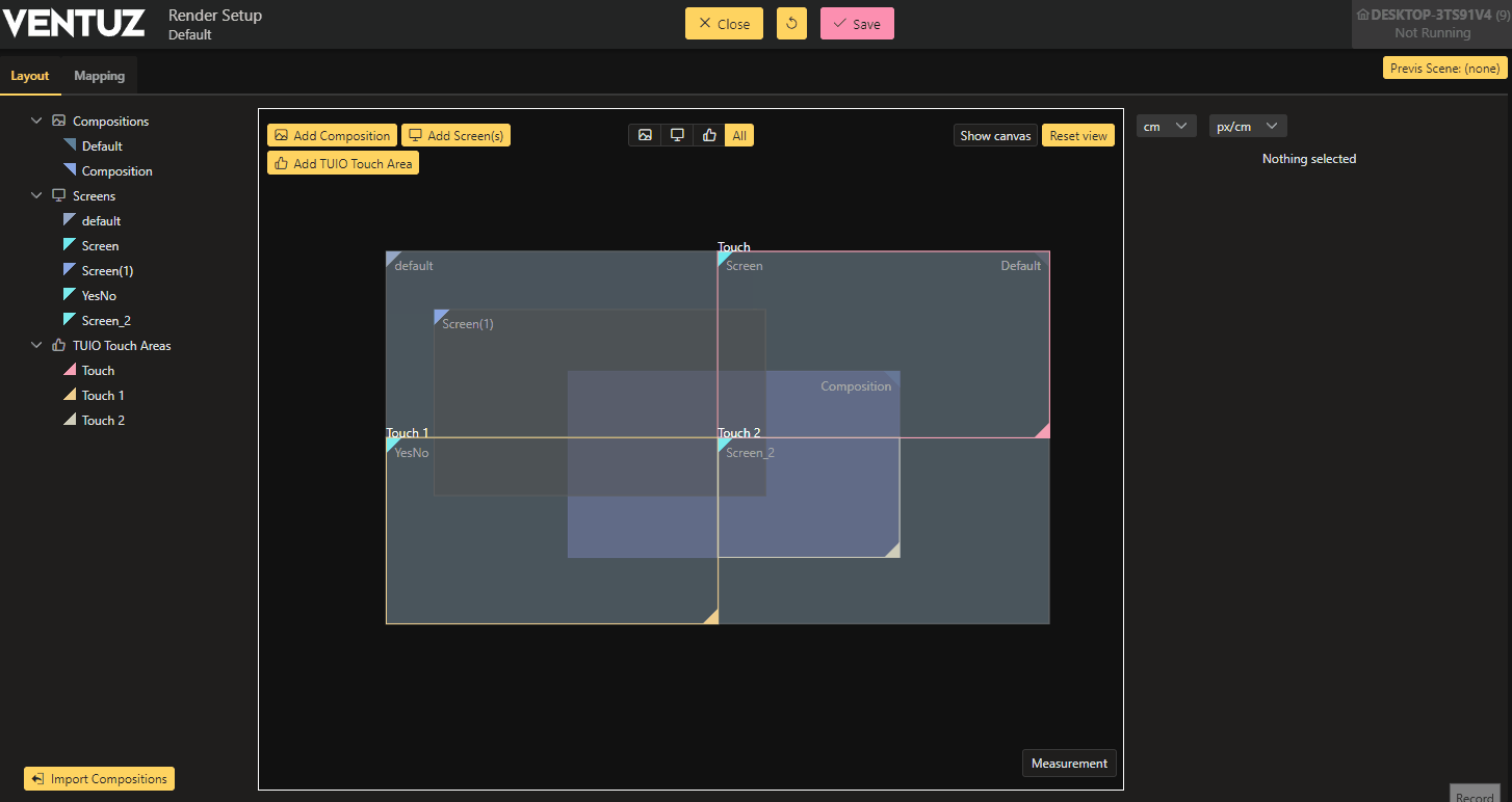 | Rotations can be snapped to 10° or 5° using CTRL(10) or ALT(5) | 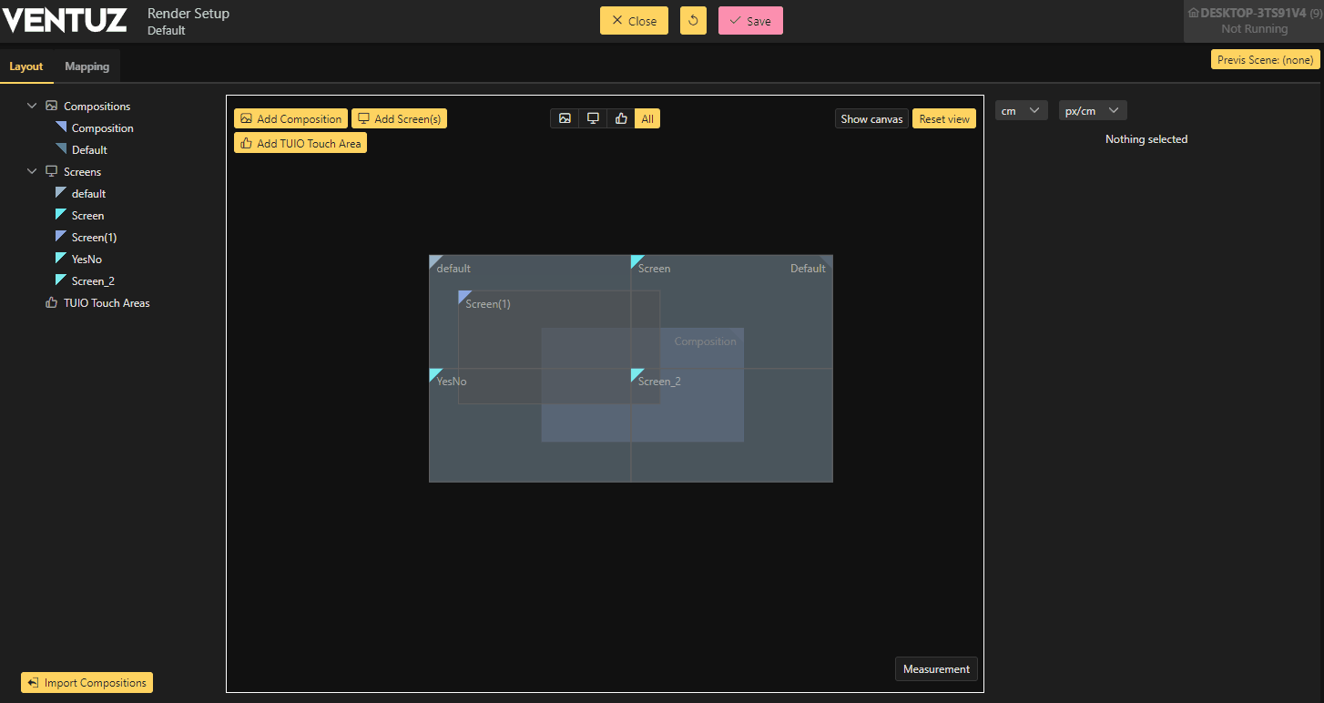
|
| Use the All mode to quickly move a bunch of elements | 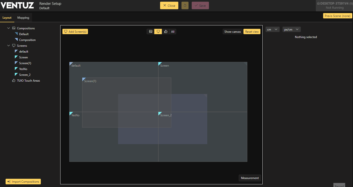 | Scaling only works for Compositions and TUIO Touch Areas, to resize screens use the Property Editor | 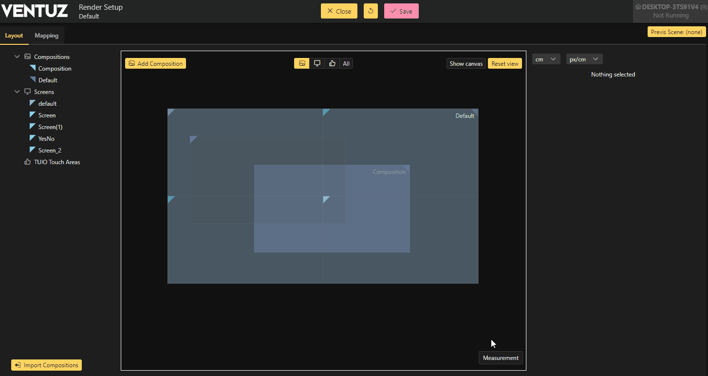
|
Bezel and Overlap
To create an equal bezel or overlap between multiple elements, use the grid function when creating new screens. You can choose to add them using centimeter values or pixels.
Bezels can be corrected anytime by using the Bezel property adjustment. Overlaps have to be manually adjusted.
It is also possible to do it like it was in Version 6 where all selected screens are properly aligned when the bezel was added. This only works when it matches the following requirements:
- They're all selected
- Have bezel on
- Have the same rotation
- Their bezels touch
Or you can pull them apart using the arrow's appearing when having selected more then one screen. This also comes with some limitations:
- Pulling apart screens which already have different distances to each other will create odd behavior
- Compositions wont scale with it unless you are using the Default Composition with fit to screen on.
Output Types
Using the Mapping Mode it is possible to change to different output types, assign multiple screens to the same output or use only specific parts of a given screen by using Cuts.
To change to different output types use the pencil button.
Single
Uses a single screen on the output. Assign a screen by drag + drop from the left pane onto the desired output on the right.
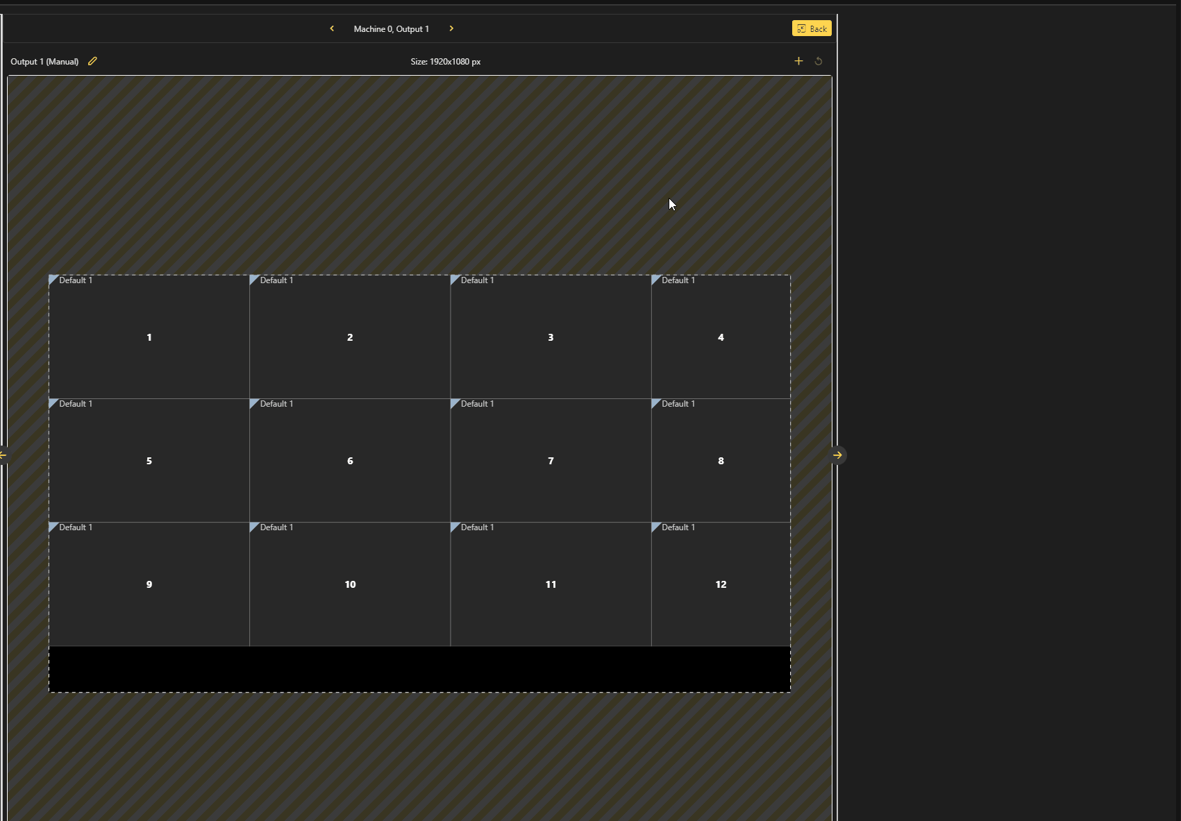
Grid
Assign multiple complete Screens to a single output in a grid which can be individually customized.
Manual
Gives the user full control of the output size, individual screen size and position. Rotating the output in 90° steps is possible here.
It is possible to use the same screen multiple times by applying them to multiple times to the same output. Notice how the original size of the Screen set in the Layout cant be overwritten by this. You can also choose which portion should be rendered, change this by changing the screen position in the left view.
While in manual mode, it is possible to link the size or aspect of the output to the individual cuts.
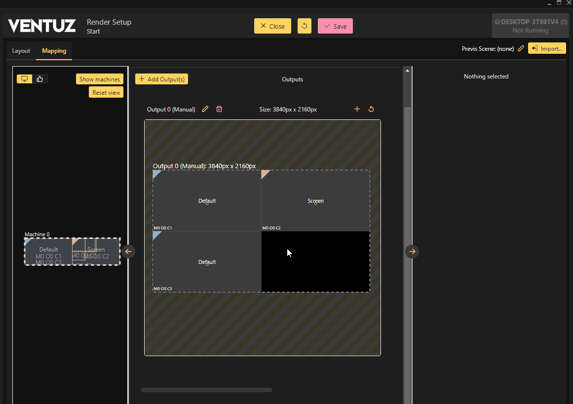
Link Size: Links the output size directly to the screen size.
Link Aspect: Links the aspect of the cut to the screen.
Unlinked: Screen and outputs are handled individually. The output will be scaled accordingly.
Overlaps wont blend! They will be stacked on the output, depending on which screen where assigned first.
It is also possible to hold down the SHIFT key when dragging screens onto a output to tile it to the desired size automatically.
Cuts
In general as soon as one uses either the Grid or Manual mode the output will be cut into multiple pieces. Indicated by the label in the middle. For the Grid mode this will show 1.1 1.2 and so on depending on there position in the output. For Manual tiling it will simply count upwards.
M0 = Machine + ID
O0 = Output + Number of output starting with 0
C1 = Cut + Number of the cut counting upwards from 1
Properties
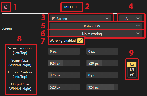
1:
- Deletes the currently selected screen from inside the output
2:
- Output label also shown on the screen itself inside the output mapping in the lower left corner
3:
- Dropdown menu to change to different screens for the output
4:
- Seperation groups
5:
- Choose the rotation of the screen inside the output. This can be also done by using the handle in the upper right corner when clicking on a screen inside a output.
6:
- Menu to enable different mirror modes for the output
*Mirror H: Mirrors horizontally *Mirror V: Mirrors Vertically
7:
- Enable or disable Warping&Shaping for the selected screen
8:
- Screen Position: displays the current X and Y position of the screen cut outside of the output.
- Screen Size: the current size of the selected screen. This can be independent from the actual output size which will be rendered.
- Output Position: the current position of the screen inside of the output.
- Output Size: actual used render size for the selected screen.
9:
- Link Size: Links the output size directly to the screen size.
- Link Aspect: Links the aspect of the cut to the screen.
- Unlinked: Screen and outputs are handled individually. The output will be scaled accordingly.
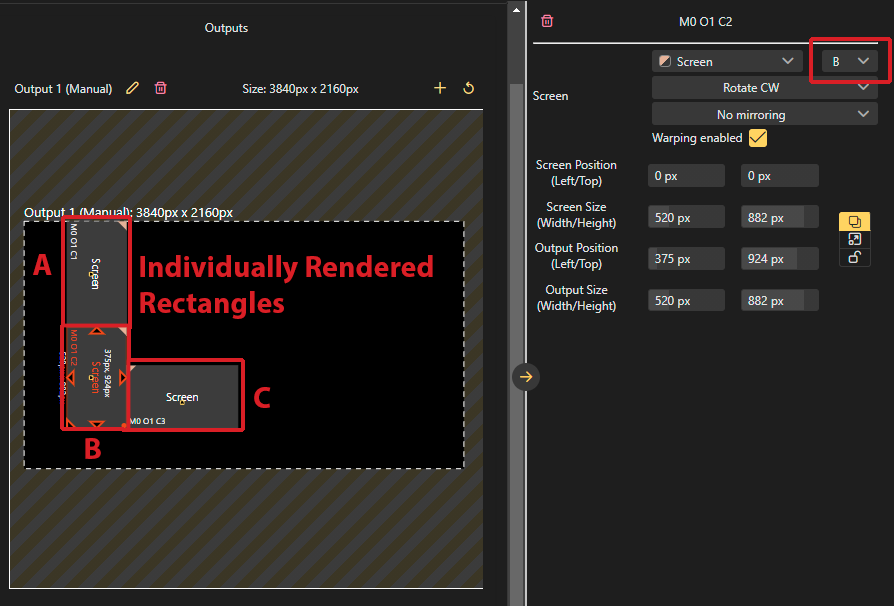
Separation
By using different separation groups for output cuts its possible to use the rendering more efficiently.
Without separation groups:
Ventuz will render everything in one single rectangle.
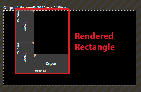
With separation groups:
Ventuz will render single screens separately.
Split and Combine
With the split button you can easily tile a screen or split them to the desired count. Or split of a specific portion of the screen. This menu is available in the properties or by onto a screen.
Machine ID
The machine ID makes sure that a Ventuz scene can determine which part of the overall clustered content will be rendered. This is done by comparing the current machine ID to the machine ID specified in the Render Setup. Currently the machine IDs are assigned automatically. If a new machine is added to an existing Render Setup configuration, the smallest free ID is taken. If you want to change the System ID of a machine, click on the small pencil while being in the Mapping mode. It is possible to setup multiple machines whether or not they're physically present or connected to the system.
TUIO Touch Area
The TUIO Touch Area allows remapping of incoming touch data to a custom area of the used #Screens. Ventuz Input Subsystem receives the touch data from attached touch devices. The touch is interpreted in normalized coordinates from 0,0 to 1,0 from the top left corner to the bottom right corner. By default, there is no TUIO Touch Area and will apply to all outputs. To specifically assign touch to either screens or outputs use the Mapping Mode.
Windows Touch is not affected by TUIO touch areas and will always span across all outputs, please use the multi gpu capabilities as well as touch groups to define specific areas which you want to limit!
Windows Touch is does work in a cluster configuration, but with severe limitations e.g: interactive Objects spanning across 2 machines wont update correct
Examples and Scenarios
Depending on the editing mode you are in it is possible to edit elements in different ways. By default, the Render Setup will always have a default #Screens and a #default Composition. Starting with the Compositions' editing mode, it will highlight the currently used Compositions. on a compositions will enable the possibility for direct scaling or rotating. Use the arrows to scale and the small dot in the upper right corner to rotate. All these options are also available inside the Propertys window on the right.
The Default Composition will always scale with the screens used on it. This is only possible in the default Composition.
In this example use the Render Setup Editor, there is a simple two screen setup where the content is spanned two Full HD screens. In Ventuz 6 this required a display span mode like Mosaic to work. Now this can be achieved using several different approaches without the need for Mosaic or Eyefinity.
In this case, add a second screen and place it right beside the default one to achieve a dual output setup.
All the settings seen in the Pop up window, except for the adding of new compositions directly, will also be available inside the property window.
Use the middle mouse button to pan the view. Or scroll the middle mouse wheel to zoom in and out. click and drag on any element this will shift it around inside the workspace. Snapping is also always on which should help you align elements easily.
As you can see the Default Compositions scaled with the new screen inserted, this wont be the case for any other composition then the default. This feature exists to make simpler setups faster and easier to achieve. It can be disabled by unchecking the "Fit to Screens" option in the properties pane.
Open the Mapping mode by clicking on "Mapping" in the top left corner to assign those Screens to the outputs we want to use. The Composition in this case is defining the area which we want to render content, therefore we need to have screens to assign to the outputs.
As you can see on the left, Ventuz doesnt know about the second screen yet, which is indicated by the white dotted line (the machine boarder). To assign it, we need to add another output to the machine, we can also directly assign the screen to it by using the drop down menu inside the pop up window. Or drag + drop screens from the left on to empty output slots on the right. If placing a screen on an output that has a screen already assigned to it, the existing screen will be replaced by the new one.
Outputs, unless configured differently, will always use the most left connector ( Or top one depending on if your pc is lying down or standing) first, and go on from there.
Now we are done and can start designing content for this new setup. Windows Touch inputs will now use both outputs. To make TUIO inputs work, assign them to the outputs by using the button below. No need to worry about any display group modes anymore! Just make sure that your Device Configuration has also two outputs configured!
Keyboard Shortcuts
Here is an overview of the available mouse and keyboard operations.
| View | ||
|---|---|---|
| Middle mouse button+drag | Pan | |
| Middle mouse wheel | Zoom | |
| R | Reset view | |
| double click | Outputs | Maximize / Restore view |
| Selection | ||
| click | Select | |
| click+drag | Rectangle Selection | |
| click | Context Menu | |
| CTRL click | Multi Selection | Add/Remove to/from selection |
| CTRL+A | Select all elements depending on the selected mode | |
| CTRL+ click+drag | Disable snapping | |
| SHIFT+ +drag | Perpendicular measurements in 45° steps | |
| Editing | ||
|---|---|---|
| move | Move selection | |
| SHIFT move | Move selection without snapping | |
| CTRL + C | Copy selection | |
| CTRL + V | Paste | |
| CTRL + Z | Undo | |
| CTRL + Y | Redo | |
| ←, →, ↑, ↓ | Move selection by 10 pixel | |
| CTRL + ←, →, ↑, ↓ | Move selection by 1 pixel | |
| SHIFT + ←, →, ↑, ↓ | Multi Selection | Change distance by 10 pixel |
| CTRL + SHIFT + ←, →, ↑, ↓ | Multi Selection | Change distance by 1 pixel |
| + drag + CTRL | Rotation | 10° snapping |
| + drag + ALT | Rotation | 5° snapping |
| CTRL+S | Save changes | |