Topology
Table of Contents
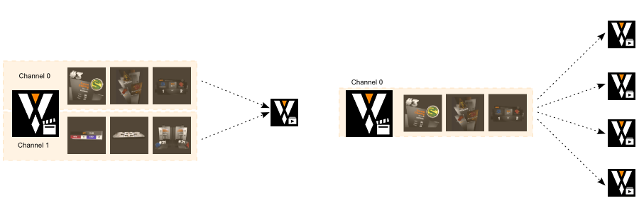
As discussed in previous chapters, one of the fundamental design principles of the Director is the separation of content and the actual rendering system via channels. A channel is a stream of content (specifically templates being cued, filled with values and taken on air). Where that content is rendered is not part of the show but part of the topology. This allows an operator to create a show, pre-fill and test playlists and timelines, create pages, develop window layouts and everything else on the go on his laptop. Once he comes to the venue where the event is taking place, he simply switches the topology and is ready to run the same show on a multi-machine setup.
So what is a topology? Think of it as a blueprint of the environment in which Director works. It defines how many machines should be in each rendering cluster, from which channel they can receive template commands and which outputs are made available to be shown in the preview windows inside Director. It does not enforce any machine setup information like machine/group IDs, the render setup to use or how the rendering pipes are configured in those machines. Instead it presents the state machines are in and visualizes potential problems.
The actual hardware/software setup of individual machines is done via the Ventuz Configuration Editor.
Topologies are usually created by the IT department in advance when the rendering machines are set up, along the lines of creating a proper render setup for a cluster or making sure the group IDs match. A Ventuz Director operator typically only selects the correct topology to run his shown on and uses the Topology Editor to monitor the environment.
Director only sends remoting commands to remote machines, no images, videos, templates and so forth. Each machine has to have its own copy of the Ventuz project including all assets and it has to be in the VMS's synchronization directory. This can be done manually or by using a 3rd party file synchronization tool or network shared folders.
The Topology Editor
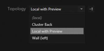
The topology editor has a special role in the user interface in that it is always part of the window layout, same as the message log. The easiest way to access it is via the topology button on the empty workbench (to the right of the topology chooser) or the same button in the show control once a show has been opened.
The editor has three distinct parts:
- the actual topology in the center
- the list of available machines on the right
- the editing toolbar at the bottom
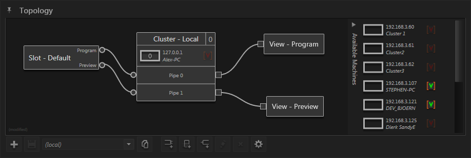
The image above shows the state of the topology editor when no show is opened. While running a show, the available machines list and the editing toolbar are automatically removed.
The editor has two distinct modes of operator, depending on whether a show is open or not. When no show is open, the topology can be edited, machines configured but nothing disturbs a Ventuz Runtime that might run on a remote machine. As soon as a show is opened, the topology can no longer be modified and Director takes control of all machines used in the topology.
The topology editor always shows the currently active topology. Same as on the empty workbench, the topology editor's toolbar contains a drop down box where all available topologies are listed. In the image above, the automatically generated default topology "(local)" is selected. It consists of one channel slot, one cluster, two views and various connections between them.
Elements in the topology can be selected by clicking on their name, adding shift or ctrl to select multiple elements. Selected elements can be moved by dragging the region where their name is shown. New elements can be added by either clicking the appropriate buttons in the toolbar or via the context-menu when clicking on the background of the topology editor. Connections between elements are created by dragging from an outlet to another outlet of the same type on another element. To change the area that is viewed,
Machines
Machines are represented by a rectangular box with their IP-address and name next to it. The following shows a cluster of three machines in various states:
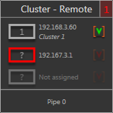
- The top machine is correctly connected via VMS (bright gray color), it has a machine ID of 1 (number inside the rectangle) and a Ventuz runtime is currently running on that machine (green V-icon on the right).
- The center machine has been assigned to the cluster but there is a problem (red rectangle). In this example, when the screenshot was created Director had failed to connect to the machine because it was shutdown.
- The last slot of the cluster has no machine assigned (faded out gray).
The same information is also available for machines that have been detected on the network but are not currently used in the topology: the list of available machines. This part of the topology editor is collapsed by default and can be opened by clicking on the label "Available Machines" on the far right side of the topology editor. For a machine to be listed here, it has to have a running Ventuz Machine Service (VMS).
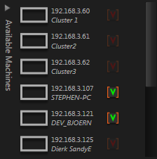
As will be seen later, the local machine has a special role and is never listed in the available machines list.
Further information about a machine is displayed when hovering the mouse cursor over the machine's name. In a similar fashion, information about the runtime is shown when hovering over the Ventuz Runtime icon.
Administration
As stated in the beginning, the purpose of the topology editor is not to fully configure a machine as that is done via the Ventuz Configuration Editor. However, since Ventuz allows having multiple viable configurations stored on a machine, the task for a Director operator is often not to create a configuration but restore it. For this purpose, some basic administration operations have been added to the context menu that can be reached by clicking on a machine.
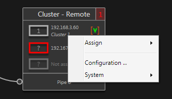
The system menu contains entries to start/stop a runtime or shutdown/reboot the whole machine. Similar operations are available when right-clicking on the cluster itself to perform them on all machines in the cluster. To change the configuration of a machine, make sure there is no Ventuz Runtime running and then select the Configuration entry (or double-click on the machine).
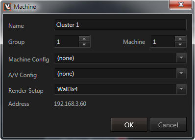
This is basically a slimmed down version of the front page of the Ventuz Configuration Editor. It uses the same mechanism to access the machine via the Ventuz Machine Service (VMS) and change the active configuration. A similar dialog is available via the Configuration entry in the cluster's context menu to edit all machines at the same time.
Cluster
Inside the topology, a machine never exists on its own but is always part of a cluster, even if that cluster only consists of that one machine. The reason for this is that the cluster provides and manages the outlets Director can connect to in order to send cueing commands or receive preview outputs.
There are various ways to create a cluster: The add cluster button in the topology editor's toolbar, the context menu when clicking on the background of the topology editor, but the quickest is to simply drag a machine from the available machines list to the background of the topology editor. Regardless of which way is used, the cluster edit dialog is opened in which a name can be given, the number of machines in the cluster is specified as well as whether it is a single or dual pipe cluster. The same dialog can be accessed by double-clicking on a cluster's name or via the cluster's context menu.
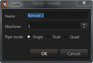
Note that the pipe count is again only a planned goal. It specifies that the machines in this cluster should have that amount of pipes, the actual pipe count is dependent on the configuration of the machine itself.
The local machine has a special role inside a topology. It is never part of the available machines list and cannot be assigned to an existing cluster. The only way to use it is to create a local machine cluster via the add cluster button or add cluster context menu entry.
Ports
Ports are shown as connection points on the left side of each pipe. The number of actually available pipes depends on the number of scene ports in the Ventuz project's layout scene. In other words, to support cueing multiple templates in parallel on the same pipe, the project has to be build for it. As with pipes, the number of ports shown in the topology is only a plan of what the operator assumes the project to be. The number of ports per pipe is a global setting on the topology and can be adjusted via the properties button at the far right of the topology editor's button toolbar.
Assigning Machines
Once a cluster has been created, the next step is usually to assign machines to it. This can be done by dragging an available machine from the available machines list to the cluster, via the context menu when clicking on the empty machine slot in the cluster or by specifying an IP address for a yet unavailable machine (also via the context menu). The order of machines inside a cluster can be changed by dragging one machine and dropping it on to another machine slot. As soon as a machine is assigned to a cluster, it's machine ID is shown inside the rectangle that represents the machine.
A machine can be unassigned by either dragging it from the cluster to the topology editor background or also via the machine's context menu.
Error State
Depending on the machines inside a cluster, a cluster can be in an error or warning state. This is shown by the color of the group ID in the top right corner of the cluster. When hovering over that number, a tooltip will list the detected problems.
Channel Slot
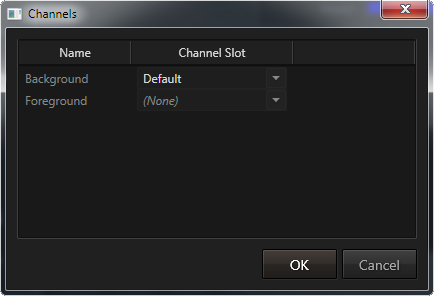
A show is completely agnostic to what topology it is running on as everything is routed through channels. But of course a channel has to know where in the topology it can send its commands to. Each channel slot represents a point in the topology where a channel can potentially be attached to. It has a program and preview outlet that can be connected to clusters but does not have any functionality per se. All it got is a name and its internal ID.
Each channel in a show has a channel slot ID it tries to connect to in the currently active topology when a show is opened. This connect is re-resolved whenever the channel is mapped to a different channel slot or the underlying topology changes (e.g. the operator switches to a different topology). The ID of a channel slot can be changed via its editing dialog by double-clicking on a channel slot or via the edit entry in its context menu. The other end - the ID a channel is mapped to - can be changed in the Channel Manager which is accessed via Show / Channels in the main menu.
Connections
The program and preview outlets of a channel slot are what is used to connect a channel to a cluster (and therefore its rendering machines). The program outlet represents what a user sees on air. As long as a Director operator only cues a template, no visual change will occur on the program port. Director only sends cueing instructs on the program outlet and waits for the operator to perform a take.
The preview outlet on the other hand receives cue/take instructions based on the template the operator is currently editing. If an operator cues a template, it will send a cue and take on the preview outlet to get the template to the visual output (and thus making it available in the preview render window).
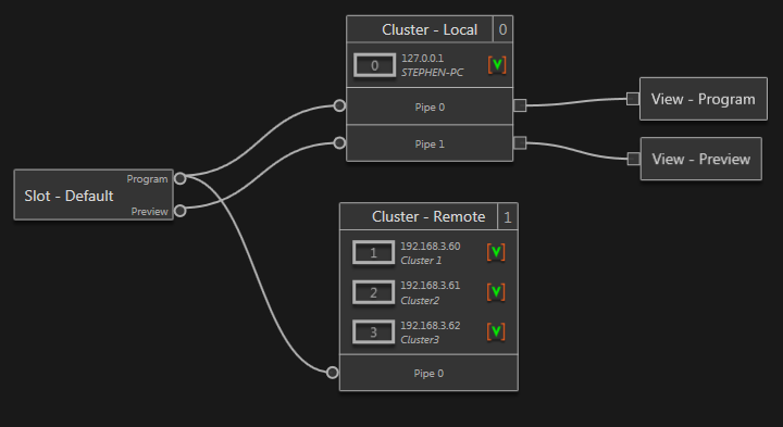
So while the preview outlet is optional, the program outlet is usually connected to Pipe 0 (the main output pipe) of one or more clusters by dragging from the outlet to the port on the cluster. The example above shows a typical case: The local machine is serving as a rendering backend for the program and preview windows inside Director. The actual output for the audience is generated on a separate, three machine cluster which doesn't even need a preview pipe. It's Pipe 0 is also connected to the program outlet of the channel slot so the local and remote cluster both create the same visual output on their Pipe 0.
Connections can be removed by either clicking on them to select them and the pressing Del or by creating a new connection using the same port which will automatically remove all connections on the same port.
View
The View elements of a topology are similar to channel slots but are used to connect visual output to renderer windows in the window layout. Again, a renderer window only stores a view ID and when a show is opened, the ID is resolved to an actual view in the topology. Which ID a renderer window is bound to can be changed in the window manager via Windows / Windows in the main menu.
Note that views have different shaped outlets compared to channel slots. The former transfer rendering output while the latter transfer cueing/take commands. One cannot connect a view to a channel slot or the template ports on the left side of a cluster.
At the time of writing, only the local cluster can provide rendering outlets.
Managing Multiple Topologies
To create a new one, use the new topology button in the topology editor's toolbar which will launch the topology creation wizard. Topologies are XML files that are stored in Ventuz's configuration folder. In fact, the actual rendering machines have no knowledge of the topology. They only receive commands from Director and are unaware of other machines. Topologies are also agnostic to what show/project they are about to run, so they are shared among all projects on a Director machine.
Next to the drop down box to choose the active topology is the button that opens up the topology manager. In this dialog, existing topologies can be duplicated or removed via the corresponding buttons or renamed by double-clicking on an entry.
Director has an application setting that decides which topology is loaded during application launch. It can be accessed via Tools / Options in the main menu. By default, the last used topology will be activated. However, it can also be configured to always start with a local setup or any specific user-created topology.
Embedding Topologies
Starting with Version 4.05, Director can also embed topologies into a Ventuz project to make project deployment to a customer easier. Topologies can be embedded to or restored from a project via the main menu entry Show / Projects / Embedded Topologies.
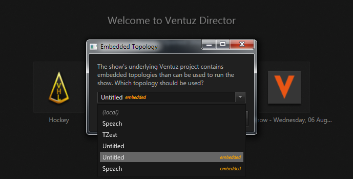
When a user opens a show, Director will check the underlying project for embedded topologies. If it contains topologies, a dialog is opened that will allow the user to switch to one of the embedded topologies. He can also switch to an embedded topology after opening a show by using the respective entry in the Topology main menu.
When embedding topologies that use remote clusters, keep in mind that opening a show with such a topology will immediately start launching Ventuz runtimes on the remote machines. It therefore can make sense to embed topologies without any machines assigned as the user will have to save and modify them locally anyway.