How To Use Tracking in Ventuz
Table of Contents
Preliminary Requirements
Camera Tracking with the FreeD protocol without a camera calibration file is possible with all licenses. In order to use professional Camera Tracking data an additional Tracking license option must be purchased and added to your Ventuz Designer or Runtime licenses.
Among the multiple Video I/O boards supported by Ventuz, there are some limitations and we have prepared a list of supported Cards. Please have a look at the the Supported Hardware Vendors Page.
Since Ventuz 7 it is possible to use multiple camera tracking streams in parallel and to map them on different cameras in Ventuz.
Tracking System Vendors
Currently Ventuz supports these Camera Tracking system vendors:
Trackmen-Egripment
German vendor Trackmen develops various camera tracking systems using various technologies. Trackmen uses in all cases the same consistent protocol for tracking data transfer, so all Trackmen systems can be connected to Ventuz, regardless of the tracking technology used.Currently, Trackmen offers these tracking products, all supported by Ventuz:
- VioTrack: Uses standard camera video feed and, depending on versions, an additional sensor camera for increased accuracy. More info here
- TalenTrack: Uses standard camera video signal to track the presenters body. More info here
- TorqTrack: Uses encoders on camera pedestals/support joints to calculate camera position in 3D space. This can be used as a kit to sensorize any existing camera support, crane, tripod, pedestal, etc.... Currently Trackmen collaborates with crane manufacturer Egripment to offer sensorized cranes and pedestals - since these systems use Trackmen technology are also supported by Ventuz. More info here
NCam
British manufacturer NCam develops Optical Camera tracking solutions that use a lightweight sensor bar attached to the camera to track natural features in the environment, allowing the camera to move freely in all locations - that makes this system especially well suited for shoulder-held or steady-cam shots, or for augmented reality projects outside of the studio. More info here
Stype
Croatian manufacturer Stype offers a sensorizing kit with auto-aim functionality, called Stype Kit, for existing cranes and jibs. The system does not require any additional external sensors or infra-red cameras and there is no need for any physical modifications of the camera crane. More info here
Mo-Sys StarTracker
British manufacturer Mo-Sys is a traditional vendor of solutions for remote heads & motion control, broadcast robotics, mechanical and optical camera tracking for AR and VR, and on-set visualization. One of the latest additions to their portfolio is an optical camera tracking system called StarTracker, which features a small sensor camera tracking a cloud of markers placed on the ceiling - that makes it mostly usable for permanent in-studio setups. More info here
FreeD Protocol
Introducing the FreeD protocol as vendor independent tracking input allows to receive tracking data from a variety of devices. The input implements the D1 data packet allowing to receive Camera ID, Pan-, Tilt- and Roll Angle, X-, Y- and Z-Position (Height), Zoom and Focus. To correct lens distortion, a lens calibration file can be loaded into the FreeD input. Contrary to the vendor specific tracking inputs, using the FreeD tracking data input does not require an additional license option to receive just the D1 data. For the lens correction an according license option is required though.
Configuring Tracking Devices
If you have the Tracking option enabled in your license, all the supported tracking devices will be displayed in the Tracking section of the Device Configuration. Please bear in mind that Ventuz does not check if Tracking systems are connected, this list only shows the supported Tracking systems.
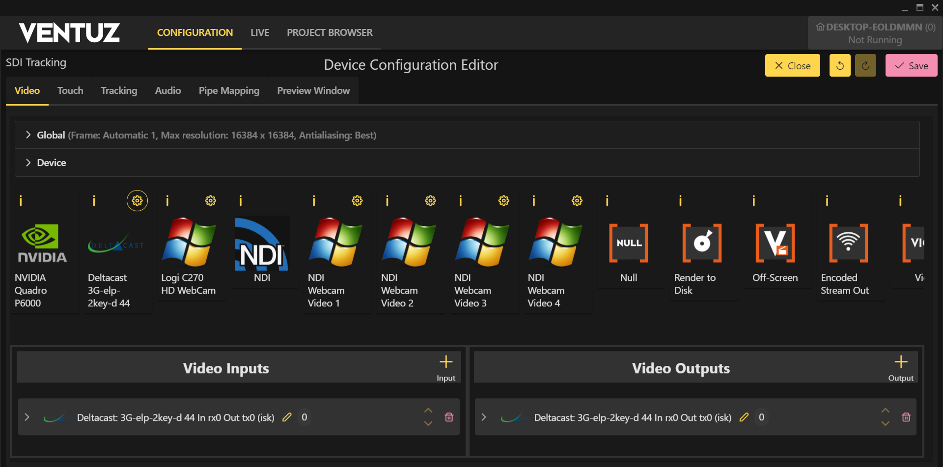
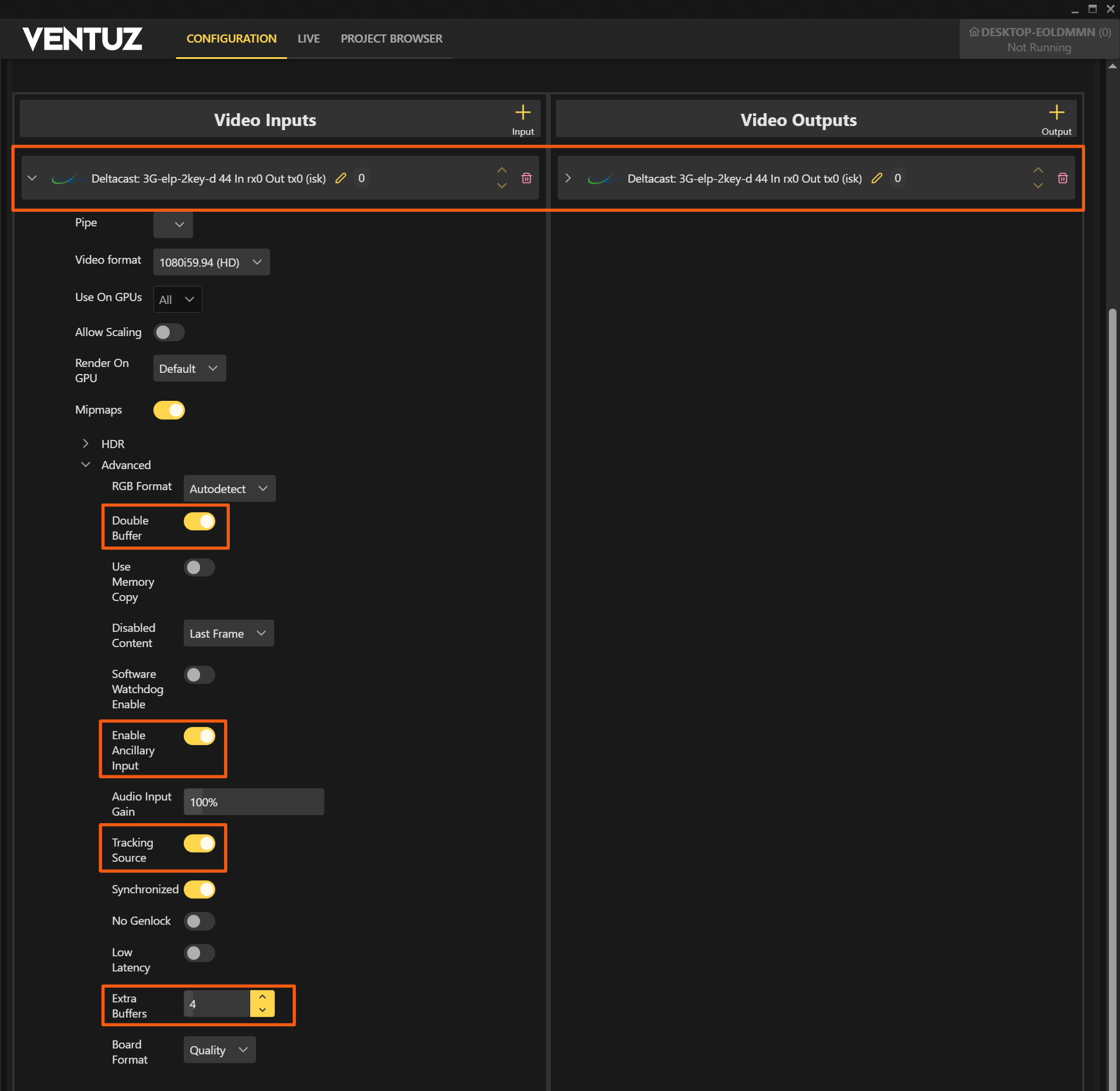
In order to configure the video device and tracking source configure the Video Input and Output in the Video section as shown and add the Tracking device in the Tracking section. For tracking you will normally need one Tracking and one Video source. Both must be placed in the Inputs pane of the Tracking or Video section and normally one Video Output device, which must be placed in the Video Outputs pane.
Depending on the Camera Tracking system of your choice, tracking data will be transmitted via Ethernet (Trackmen/NCam/Stype/FreeD) of using Serial connections (Mo-Sys). Therefore, when you add the tracking systems in your Configuration Editor, these are the options available, and how to set up tracking data transmission to Ventuz system.
Trackmen/NCam/Stype/Mo-Sys/FreeD - Ethernet interfaces
![]()
In order to set up the tracking data communication expand the settings of the Tracking device. (A in figure above).
Depending on the Tracking device different parameters will be shown
For tracking systems using Ethernet infrastructure two parameters will be available, currently the supported tracking systems that use IP Communication for the tracking data are Trackmen, NCam, Stype and FreeD:
- Tracking IP Port: Use this text field (B in figure above) to set up the local Port used to receive the UDP tracking data stream.
- Tracking IP: Use this text field (C in figure above) to set up the IP address of the machine network adapter used to receive the UDP tracking data stream. Follow the standard IP address formatting as appears in the example. Attention: For Trackmen, Stype and FreeD it is the IP of the local network adapter of your machine used to receive the tracking data as this is UDP. For NCam the IP of the machine that sends the tracking data is needed, as this is TCP.
- Since Mo-Sys supports both Serial as well as Ethernet interfaces with the Tracking Protocol you can adjust which one to use.
Mo-Sys - Serial interface
![]()
For tracking systems using Serial Communications infrastructure two parameters will be available, currently the only supported tracking system that uses Serial Communication for the tracking data is Mo-Sys StarTracker:
- Comm Port: Use this text field to set up the local Comm Port used to receive the tracking data stream. Please, bear in mind that you must follow the same formatting that appears in the example - i.e. "COM1".
- Baud rate: Use this drop down menu to set up the Baud rate of the Serial Port used to receive the tracking data stream. Currently Mo-Sys only supports the two Baud Rate options in the list, 57600 and 38400.
- Since Mo-Sys supports both Serial as well as Ethernet interfaces with the Tracking Protocol you can adjust which one to use.
Common Tracking device Parameters
- Format: A drop-down menu, this has no real use for now, will be useful for future development. Default and only value is Auto Detect.
- Mipmaps: A checkbox, this has no real use for now, will be useful for future development. Default value is ON, you can leave it like that.
- Milliseconds Delay: A textbox used to set the Tracking data delay measured as Milliseconds. The delay is applied on the incoming timestamp of the tracking data package. Setting a delay will shift this timestamp and the data will be used for the according rendering frame. In a case of jittering tracking data (inside Ventuz), which can occur when the applied timestamp is in the middle of two frames, a slight delay can clear the jitter. It can be used independently or combined with Field Delay below - both values are added. Default value is 0. The delay has to be set with negative numbers!
- Field Delay: Same delay logic as explained above, but the measure is in fields. Default value is 0. The delay has to be set with negative numbers!
- Scaling: A slider to adjust the tracking position scaling. Default value is 1.
- Lens Distortion: A checkbox, used to select if Automatic Lens Distortion is applied. Default value is ON, for most cases you can leave it like that.
- Advanced Settings: A foldable menu that feature some additional settings like:
- RGB Format: This has no effect for tracking inputs.
- Synchronized: A checkbox, used when input and output are genlocked, in that case this should be ON. Default value is OFF
- Low Latency: This has no effect for tracking data inputs. A checkbox, used to reduce Ventuz system latency by reducing the amount of frames buffered, which results in slightly better performance, in general it's better to leave it as the default OFF value.
- Extra Buffers: This has no effect for tracking data inputs. A textbox used to set add extra frame buffers to avoid possible frame drops, but results in higher system delay. Works in both Normal and Low Latency modes, and the default value is 0.
Vendor specific Parameters
Apart from the above settings which are common to most Tracking systems, some of them feature specific parameters due to some unique capabilities.
Trackmen
- Tracking Camera ID: A textbox used to set the ID of the Tracking Camera - Trackmen system allows using more than one camera. Default value is 1.
- Tracking Studio ID: A textbox used to set the ID of the Tracking Studio - Trackmen also supports multiple studios. Default value is 1.
NCam
- Use SDI Timestamps: A checkbox used to receive Ancillary data on the SDI input - A very unique NCam feature, Ventuz is the only system in the market that currently supports it. Default value is OFF.
FreeD
- Lens Calibration File: The FreeD tracking input implements only the D1 data packet allowing to receive Camera ID, Pan-, Tilt- and Roll Angle, X-, Y- and Z-Position (Height), Zoom and Focus. To correct lens distortion, a lens calibration file can be loaded into this property. For description of the lens calibration file see OpenCV Lens Calibration File for FreeD.
- FOV X: Sets the horizontal field of view in degrees. The FOV value is not included in the FreeD D1 packet, thus have to be set manually if no lens calibration file is used. If a lens calibration file is provided, the field of view from the according calibration point is applied and overrides this FovX setting.
- CCD Width: Sets the width of the cameras sensor size in millimeters. As described above, this only needs to be set manually if no lens calibration file is provided.
- CCD Height: Sets the height of the cameras sensor size in millimeters. As described above, this only needs to be set manually if no lens calibration file is provided.
Configuring Deltacast 3G-elp-2key-d
This guide is also applicable for other boards, depending on the support modes and vendor.
Ventuz can be used in 2 basic modes (not only for tracking):
- Internal Software Key: With a camera feed to key internally in the Ventuz engine, producing a composited output. In this mode the tracking data to video timing is adjusted to ensure that the video output of Ventuz is accurate.
Video and tracking data delays will be different. These delays are also dependent on cable lengths and intervening equipment in the signal pathways, so each installation will be different.
The Ventuz implementation allows two methods of locking the tracking data to the correct video frame. The particular method to use depends on wether the camera stream has accurate timecode embedded in it.- Timecode: The timecode has to be generated from either the main camera, or from a timecode generator inline between the camera and the Tracking / Ventuz systems. Tracking system extracts the timecode from the incoming video frame and assign it the tracking data sample for that frame. That timecoded tracking data is then supplied to Ventuz. Ventuz will also decode the timecode on the incoming video frames, and assign the correct tracking data packets to the specific video frame to ensure that the virtual graphics are always correctly in sync. This is only supported by NCam
- No Timecode: There is no way to uniquely identify tracking data packets to match specific video frames, so the alignment requires some manual adjustment of tracking data delays. Tracking data packets are streamed by the tracking system, Ventuz receives video frames and tracking data packets, and internally timestamps these based on the arrival time at the Ventuz computer. The tracking data is then applied to the video frame with the closest matching system arrival time. Ventuz maintains tracking data buffers than can be used to delay and “lock” the tracking data timing to the rendering. The "lock" is done by having a network system, which has a constant delay. For setups without vast routing this is the case. The adjustment is done by adding a negative delay number on the Field / Millisecond Delay. This can delay the tracking data, if the rendering is ahead the video. If the video is ahead use an external delay hardware before the Ventuz machine or use a simple video in and out as described below.
- External Key: With a video feed locked to house reference to produce key and fill channels for external keying and compositing in a downstream keyer/mixer. In this mode the tracking data and video timing is adjusted so that the AR graphics are locked to the video at the output of the keyer/mixer. The adjustments to align the camera SDI stream to the Ventuz rendering are done in the external mixer.
Note for Internal Hardware Keying: It is not possible to delay the incoming SDI video signal hardware-wise to align to the Ventuz rendering, when using internal hardware keying. The video input will be most likely ahead of the Ventuz rendering when directly keyed together on the hardware of the SDI board. So better use Internal Software Keying or External Keying.
As an alternative you can use a standard input and output and key inside the scene with a Live Video Layer This is to choose if the board does't support internal keying and there is no external keying equipment, although these methods are to preferred. In a case of the video is ahead the tracking data, and no external delay equipment avaible, use a Live Video Layer and apply a Layer Delay Effect to delay the incoming video.
In most cases Video and tracking data delays won't be equal. These delays are also dependent on cable lengths and intervening equipment in the signal pathways, so each installation will feature different delays.
Tracking without Timecode
This section is for the main tracking vendors without a Timecode implementation.
Setting Up No Timecode Mode – Ventuz Internal Software Key
- Create a cube in Ventuz Designer and position a corner at the origin.
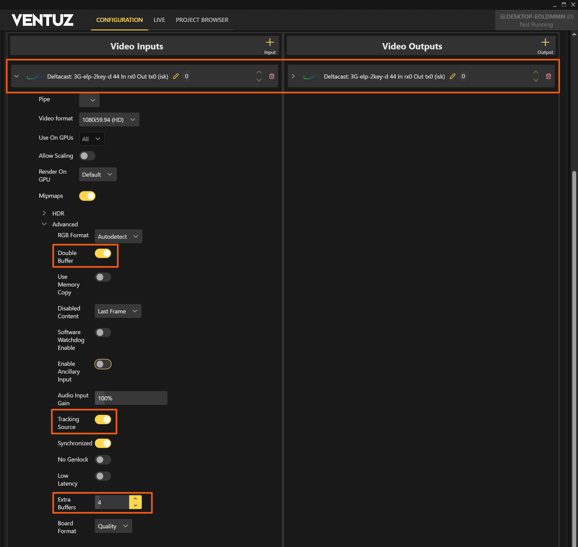
- Set Tracking Source. This will cause the tracking data to be aligned to this input
- Set Synchronized.
- Pan the real camera left and right to check the timing.
- Check the accuracy of the timing in Ventuz. If the video moves the cube, then you need to delay the video stream before the Ventuz Machine with external hardware or use the internal Layer Delay Effect to delay the signal within Ventuz. Best practice is to delay the signal with n frames, to be slightly behind the rendering and go to the next point.
- If the video moves after the cube, then you need to delay the tracking data using both Milliseconds Delay and/or Fields Delay controls in the tracking system parameters of Ventuz Device Configuration Editor. Note: The delay has to be set with negative numbers!
- Once the timing is accurate, it should remain locked.
In a case of the video input signal being ahead of the rendering and there is no external hardware to delay, switch to a standard input and output mode, as described above, and key within the Ventuz Scene. Apply a Layer Delay Effect, so the video is very-slightly behind the rendering and apply a delay on the tracking data to exactly sync.
Setting Up No Timecode Mode – Ventuz External Key
- Create a cube in Ventuz Designer and position a corner at the origin.
- Create a SDI external keying output stream
- Ventuz needs a SDI signal to align the tracking data packages, so create
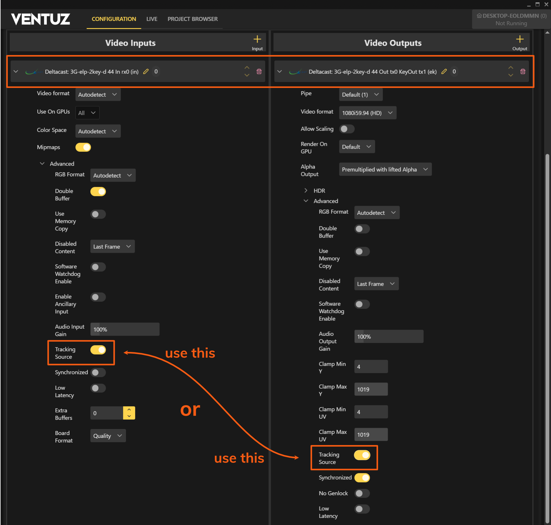
- A: an SDI input stream with the camera signal and enable Tracking Source.
- or B: use a external genlock on the SDI boards reference input and set the Tracking Source flag on the output stream. You need to define the Genlock Source in the device settings as shown in the next screenshot.
- Remove any Tracking Data delay values in Ventuz Configuration Editor
- Check the output of the keyer/switcher and Pan the real camera left and right to check the timing
- Add external video delays until the AR graphics and video are synchronized.
- As you can only add complete fields or frames in the external video delay box, you may have to delay the video so that it just starts after the graphics, and then adjust the Tracking Data Milliseconds Delay to compensate. Note: The delay has to be set with negative numbers!
Tracking with Timecode (Ncam)
Setting Up Timecode Mode – Ventuz Internal Software Key
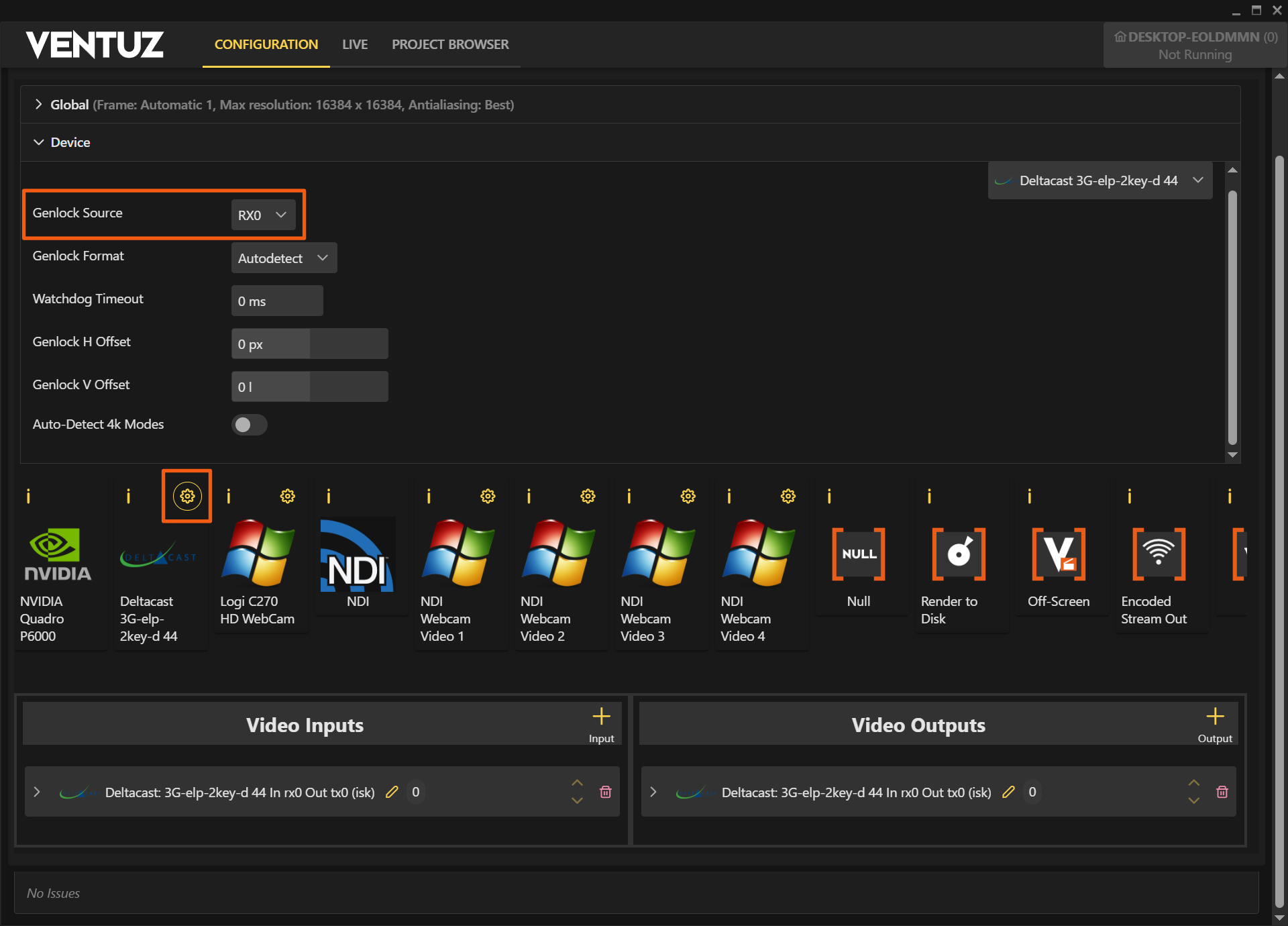
Genlock Source settings for Deltacast board
Deltacast Video input for Timecode mode (Ncam Tracking):
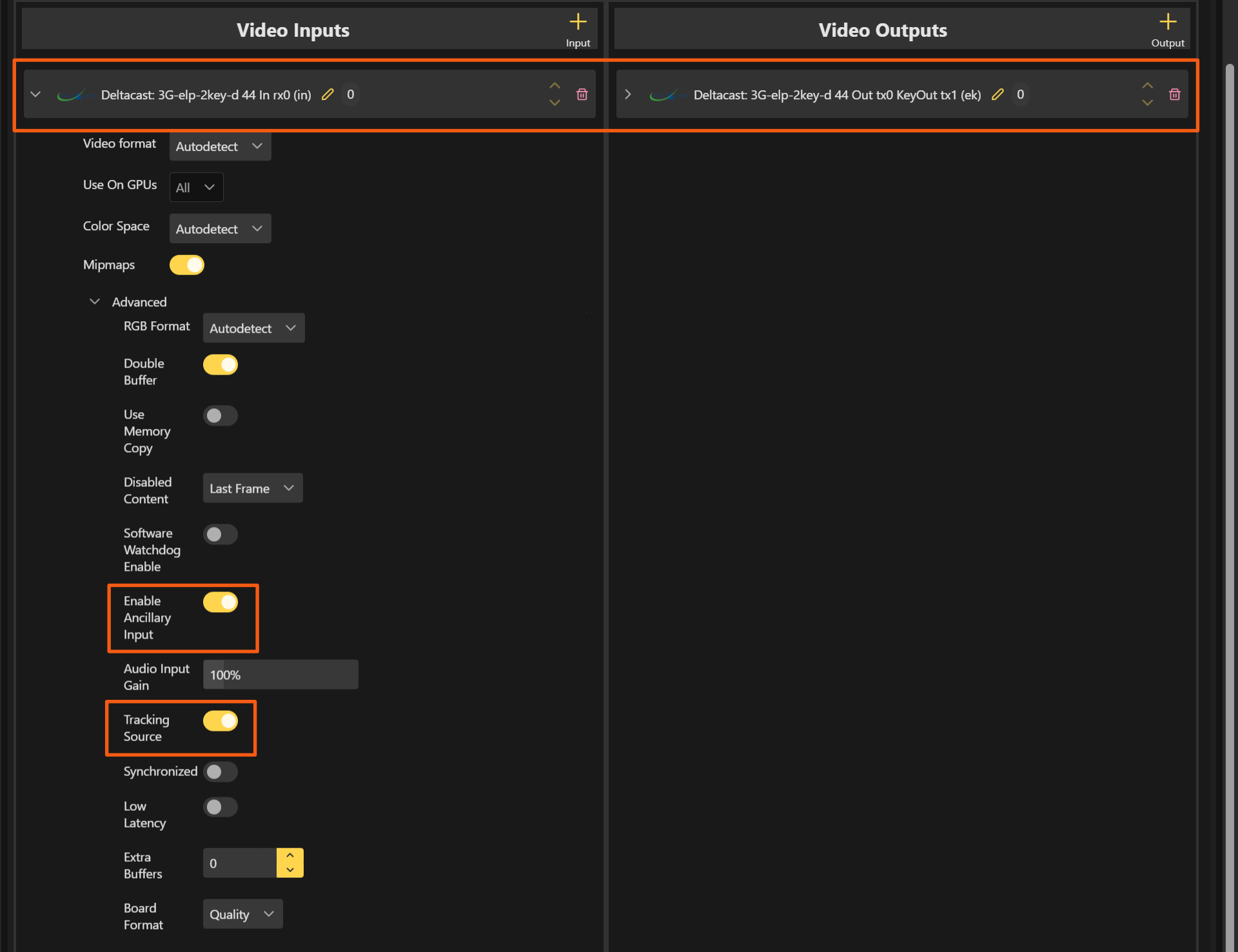
- Check the Deltacast settings in Ventuz from the attached screenshots.
- Set the Enable Ancillary Input to enable the reading of timecode from the video stream (see above).
- Set Tracking Source. This will cause the tracking data to be aligned to this input
- Set Synchronized.
- Create a cube in Ventuz Designer and position a corner at the origin
- Pan the real camera left and right to check the timing.
- The video signal has to arrive after the tracking data, that Ventuz can render the correct frame and then keyed together according to the included timestamp. If the video arrives before or simultaneously, Ventuz will key together with closest time-stamped frame/tracking package avaible.
- Thanks to the input timestamp the rendering and the live-video should stay in sync!
Setting Up Timecode Mode – Ventuz External Key
Even when using external keying we need an input SDI signal from the camera with the time code included.
- Set the Enable Ancillary Input to enable the reading of timecode from the video stream (see above).
- Set Tracking Source. This will cause the tracking data to be aligned to this input
- Check the Deltacast input board settings in Ventuz Configuration Editor from the above screenshot to set External Keying.
- Create a cube in Ventuz Designer and position a corner at the origin.
- Remove any Tracking Data delay values in Ventuz Configuration Editor (see screenshot)
- Check the output of the keyer/switcher and Pan the real camera left and right to check the timing
- Add external video delay before the Ventuz input, so the Ventuz renderer can align the tracking to the timecoded video.
- Thanks to the input timestamp the rendering and the live-video should stay in sync!
You will need to adjust the frame delay in the external keyer / video mixer.
Using external Camera Tracking Data
Once you have set up the tracking data sources and the correct synchronization (see above), now you are ready to use the external Camera Tracking and Lens Distortion data to drive the virtual camera into your Ventuz scene.
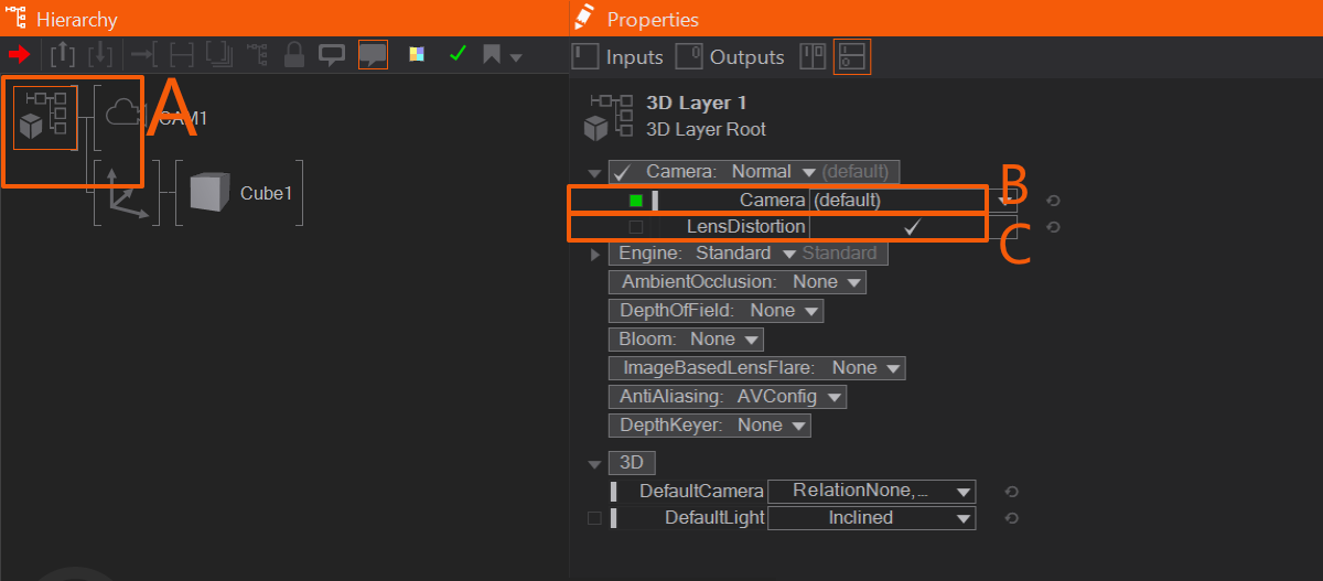
In order to do so, just create a 3D Layer in Ventuz Layer Editor. As you can see in figure above, if you get into the 3D scene Properties, by clicking on the 3D Scene Root (A in figure), the contextual Properties will appear in the Properties Editor to the right.
If you expose the 3D Camera Properties, you will get two fields, first one being a Camera dropdown menu (B in figure above) that displays the camera being used - the (default) camera is the start option, and Ventuz will always map this Camera to the Tracking Device. If you have only one Tracking device configured, this mapping will be correct and the (default) camera can be used. You can change this setting to another, non-tracked Ventuz camera, that your camera is not tracked anymore. When multiple tracking devices are configured, it might happen that the (default) Camera is not mapped to the first tracking device. To have full control, it is recommended to assign the cameras manually to a Tracking Ordinal to have full control.
The other control available, Lens Distortion (C in figure above), is just a checkbox that controls if Lens Distortion data is applied or not.
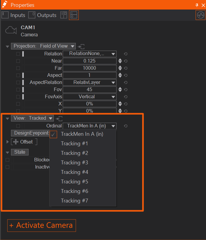
A different way of using the incoming tracking data stream is to create a Camera, change the View property to Tracked and assign the correct tracking data stream. Dont forget to Activate your camera, or change the Camera property (B in figure above) to your desired camera. This is necessary, if you use multiple camera tracking inputs.
If you have a Tracking Device configured it is always mapped to the (default) Camera of each 3D Layer. In order to not use the tracking data on a layer you need to create an extra Camera and activate it, to not use the (default) Camera.
Multiple Camera Tracking
Since Ventuz 7, Ventuz supports multiple camera tracking devices simultaneously. To add another device, simply add an input in the Tracking section of the Config Editor. The tracking devices are mapped internally on the Ventuz Ordinals. This order is not the same as the order of configuration in the Tracking config.
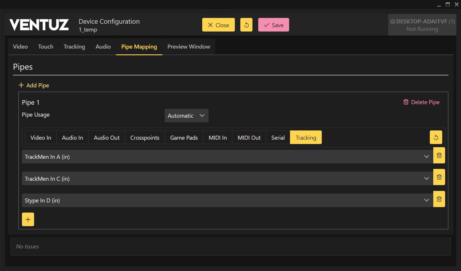
By changing the Tracking device in the dropdown menu, a different device can be mapped to Ordinal #0. The Ordinals are top to down incrementing from 0 (0, 1, 2,...). For more information see the Pipe Mapping section in the Device Configuration.
In Ventuz Designer the tracking devices only need to be assigned to the Cameras. These can be done as shown above by selecting the View as tracked and the Ordinal of the tracking device. The cameras in the Compositions can be controlled independently by their tracking devices. With playing out to different outputs, one machine is capable of rendering multiple streams controlled by their own tracking data.
To render the same scene with different camera positions it is best to use the Screen Render Options Node together with a basic Previsualization Scene. With the Screen Render Options node Ventuz can perform a camera override to the Screen node. The existing camera will be overwritten with the camera data from the tracking device. This can be done for each Screen independently, while they are bound to the same Previs Canvas and Composition. The Composition Layer is independent of the multi rendering.
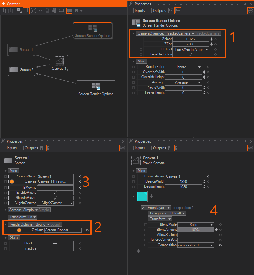
Every Screen node needs an own Screen Render Options Node, which is set to Camera Override:TrackedCamera and the desired tracking ordinal. (see no. 1) The Screen node is set to bound Render Options with the Screen Render Options node bound to the property. (see no. 2) For each Screen independently. The Screen will render now the Previs Canvas with the camera override. In order to have the right Composition(s) connected, a Previs Canvas node needs to be connected. (no. 3) In this example the canvas only consist of one Composition Layer. (no. 4)
To use this Previs Scene, import it to your Render Setup and activate it. Now, only the output mapping needs to be done.
With this simple Previs Scene, one Composition can be rendered multiple times from different camera positions. This also can be used for rendering multiple times with non-tracked cameras.
For a Multi Pipe scenario, the tracking devices are assigned for each pipe independently and therefore the second pipe can use a different device than the first one. For more information refer to the Pipe Mapping section in the Device Configuration.